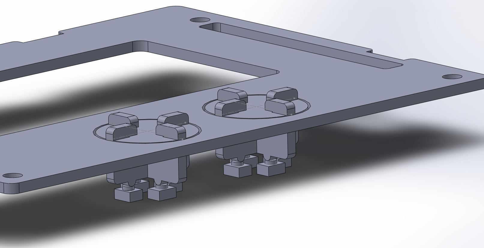
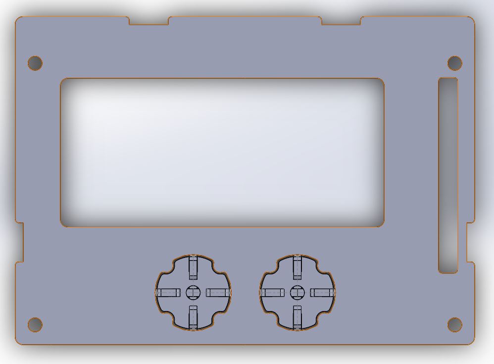
Good news for the fat-fingered!
I’ve figured-out how to make gamepad buttons out of 2mm glued acrylic sheet. Still, have to get a prototype made - I have no idea if they’ll be sticky, or end up mashing 3 buttons at once. But its a good start.
Good news for the fat-fingered!
I’ve figured-out how to make gamepad buttons out of 2mm glued acrylic sheet. Still, have to get a prototype made - I have no idea if they’ll be sticky, or end up mashing 3 buttons at once. But its a good start.
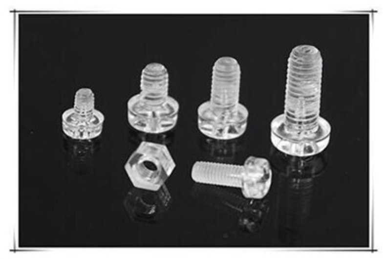
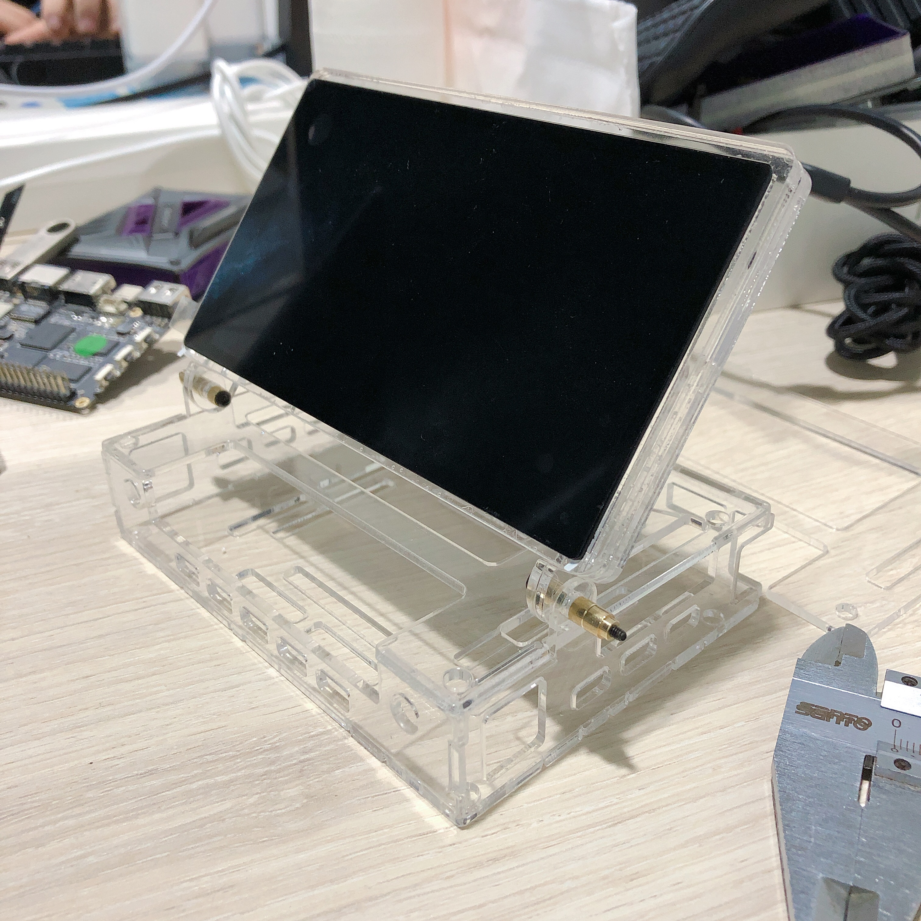
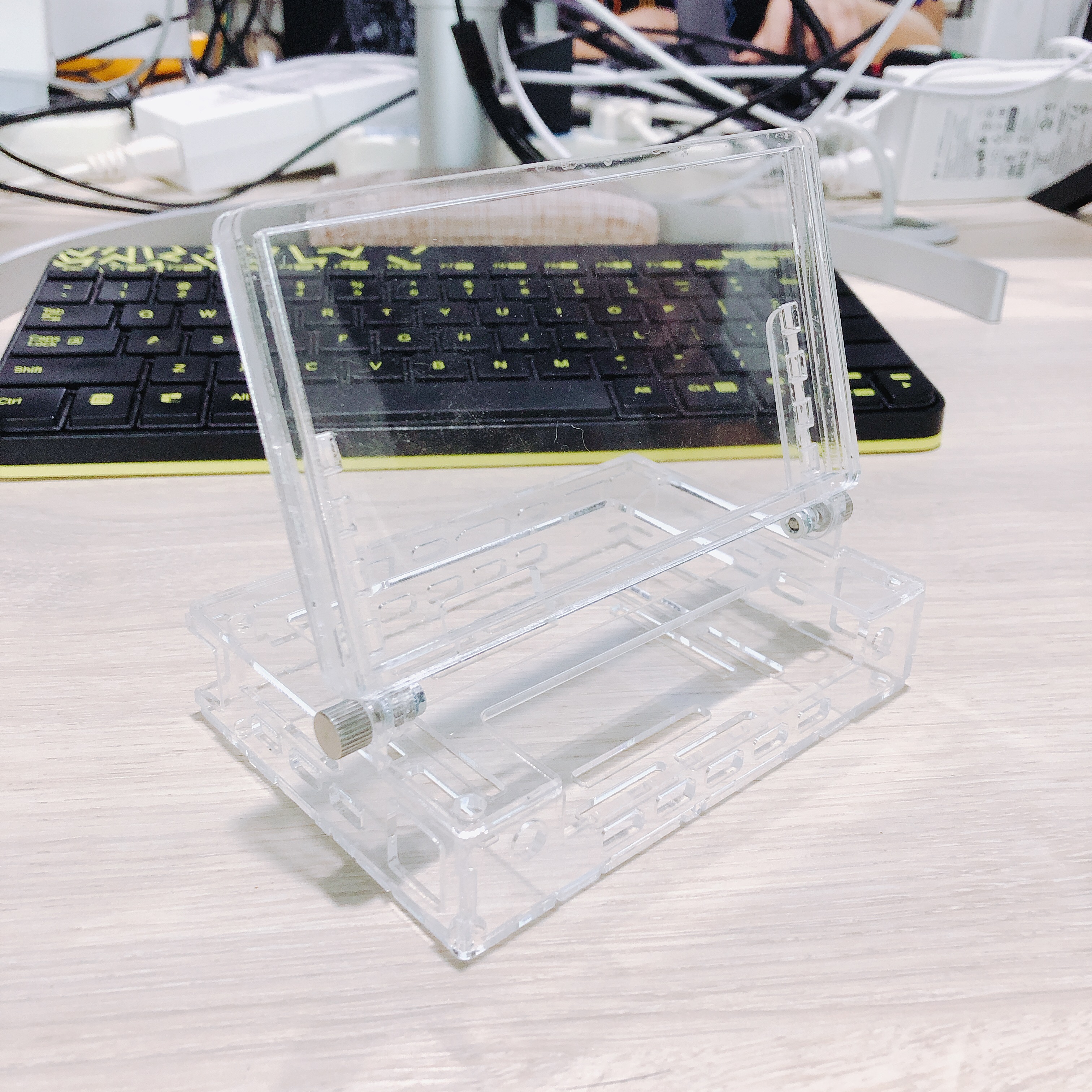
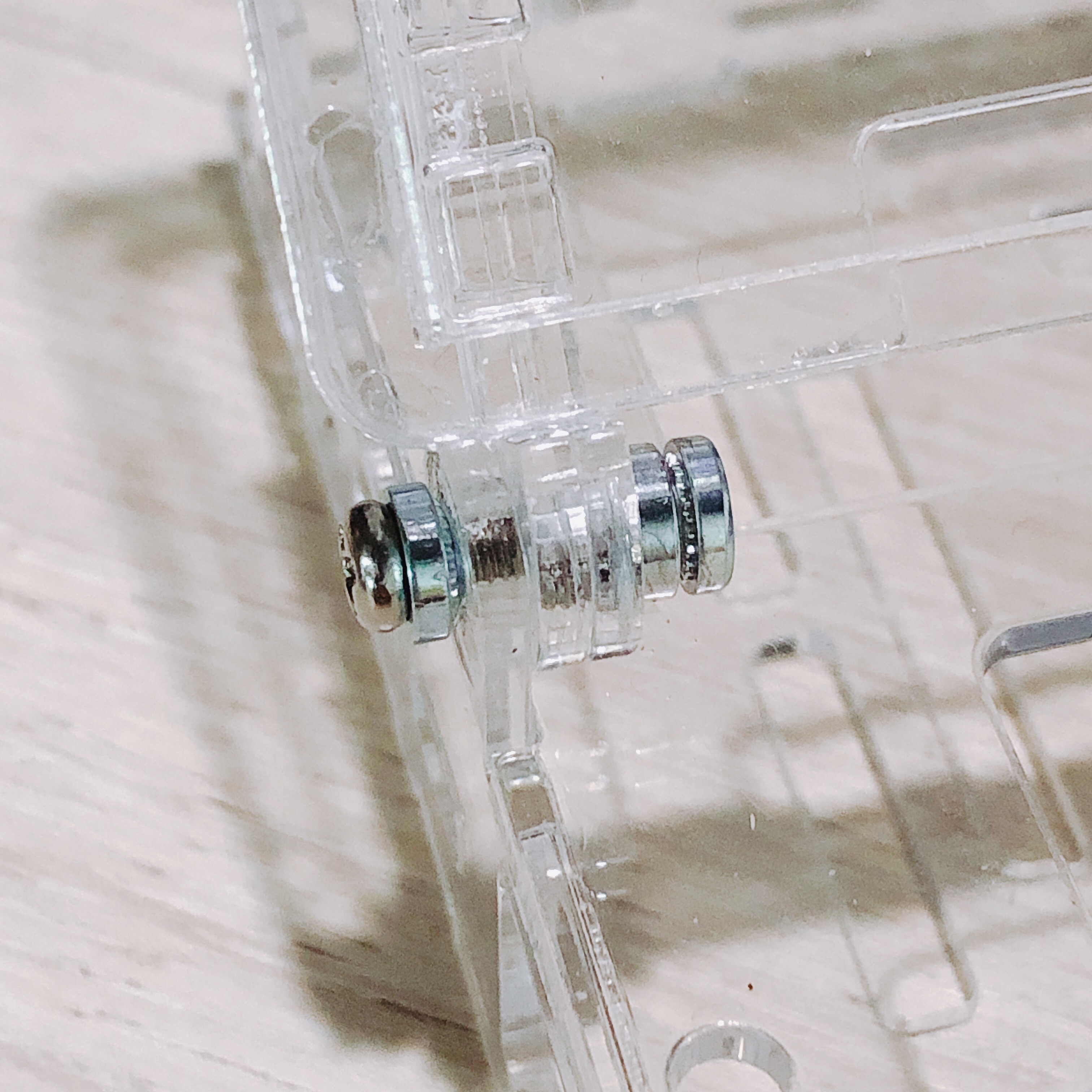
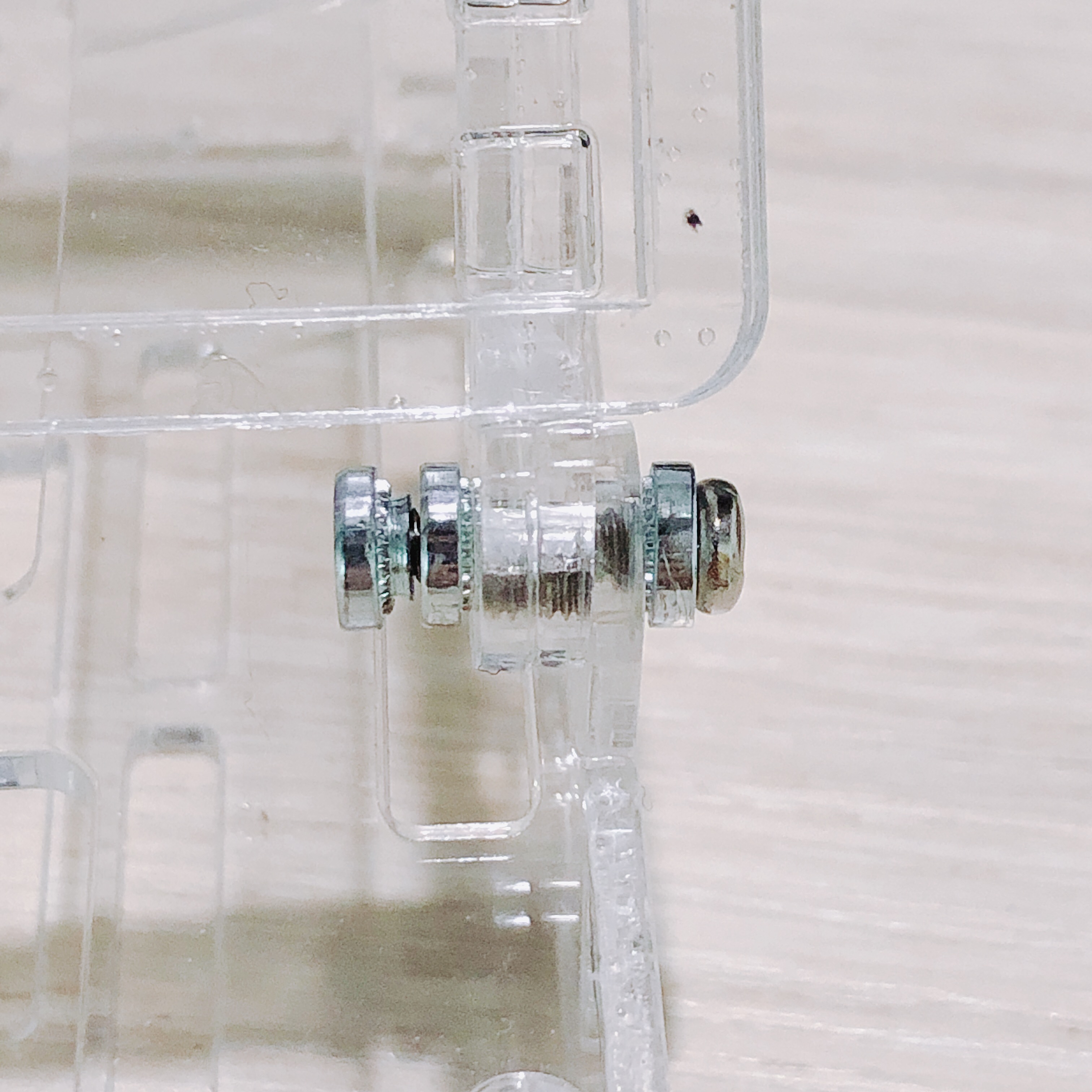
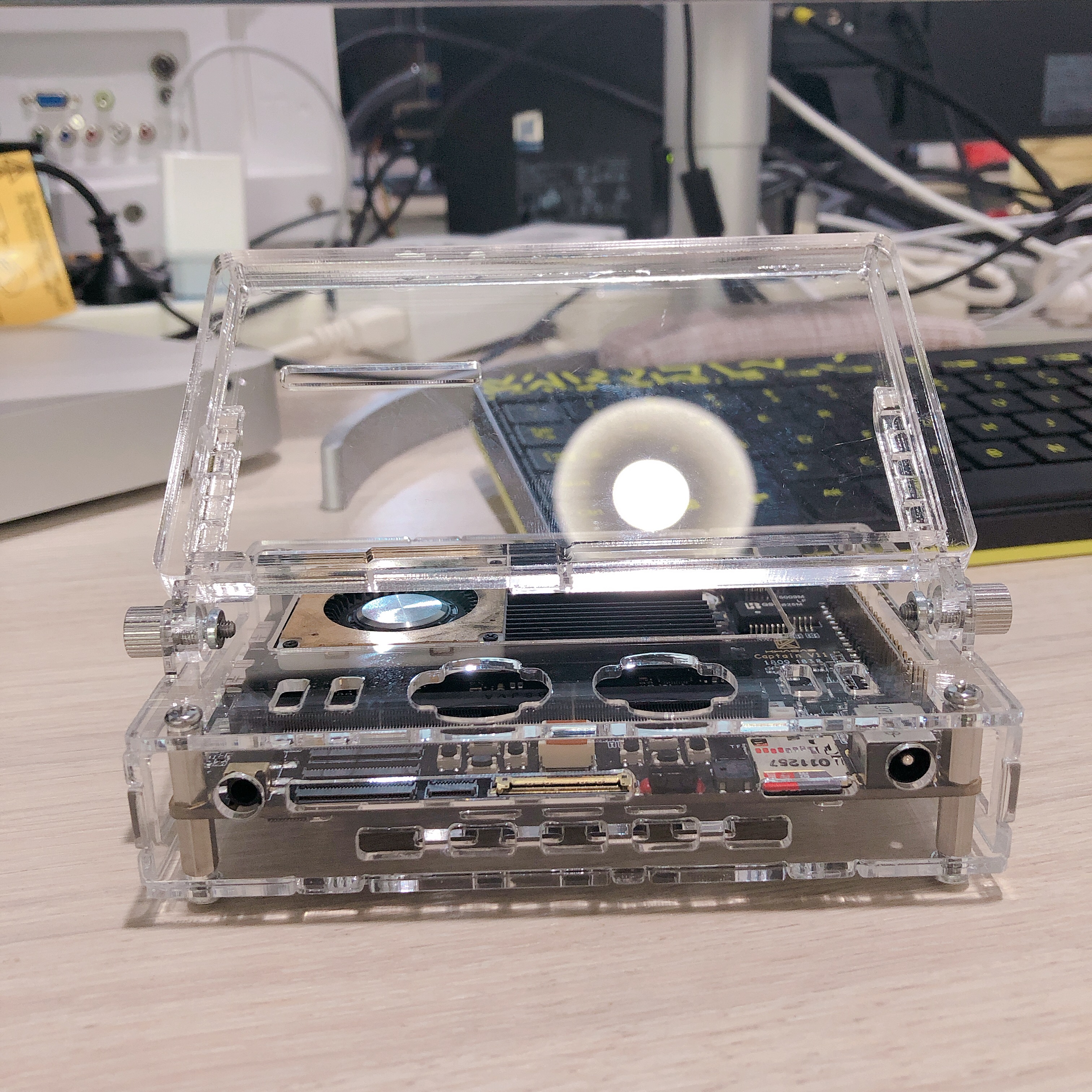
Looks and feels pretty strong. Now looking at these plastic screws…I’m thinking that since the whole casing is plastic, might as well use plastic fasteners to reduce any possible body-to-body chafing / friction.
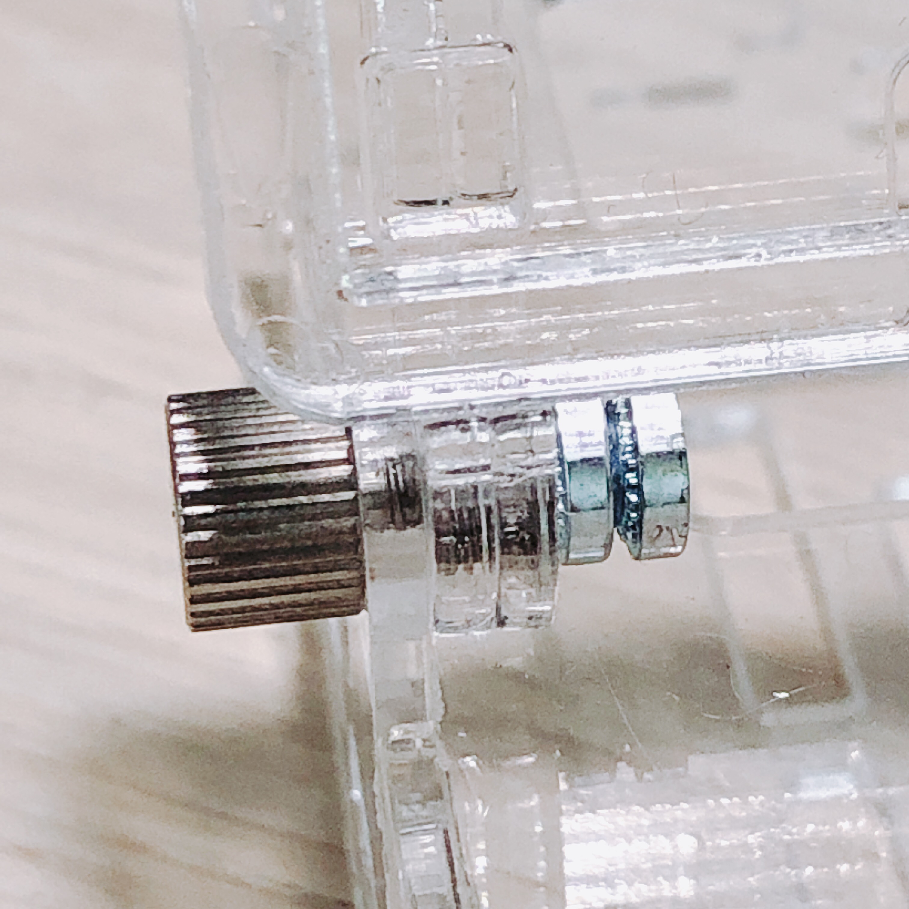
Experimenting with different screw configurations, these 2 don’t loosen-up quickly, about 50 to 100 vigorous twists are necessary to loosen it up.
This one makes a squeaky noise though, annoying. The innermost nut drops off after a while, however it works fine with just 2 nuts.
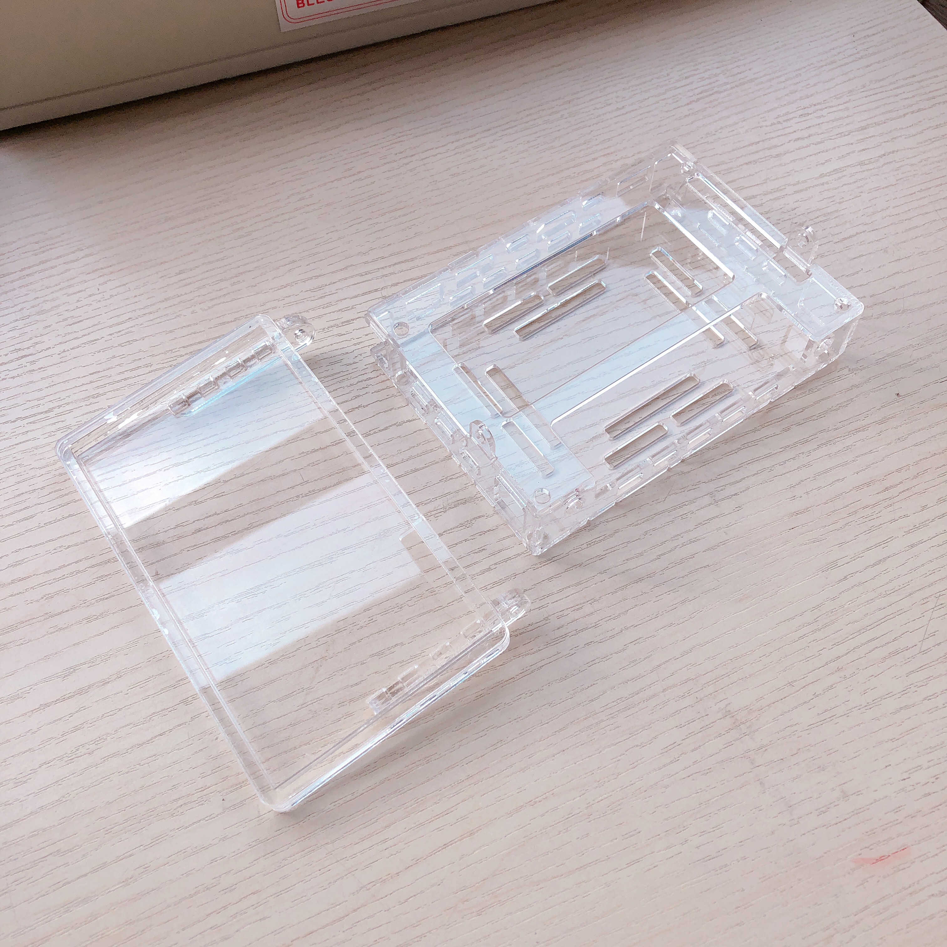
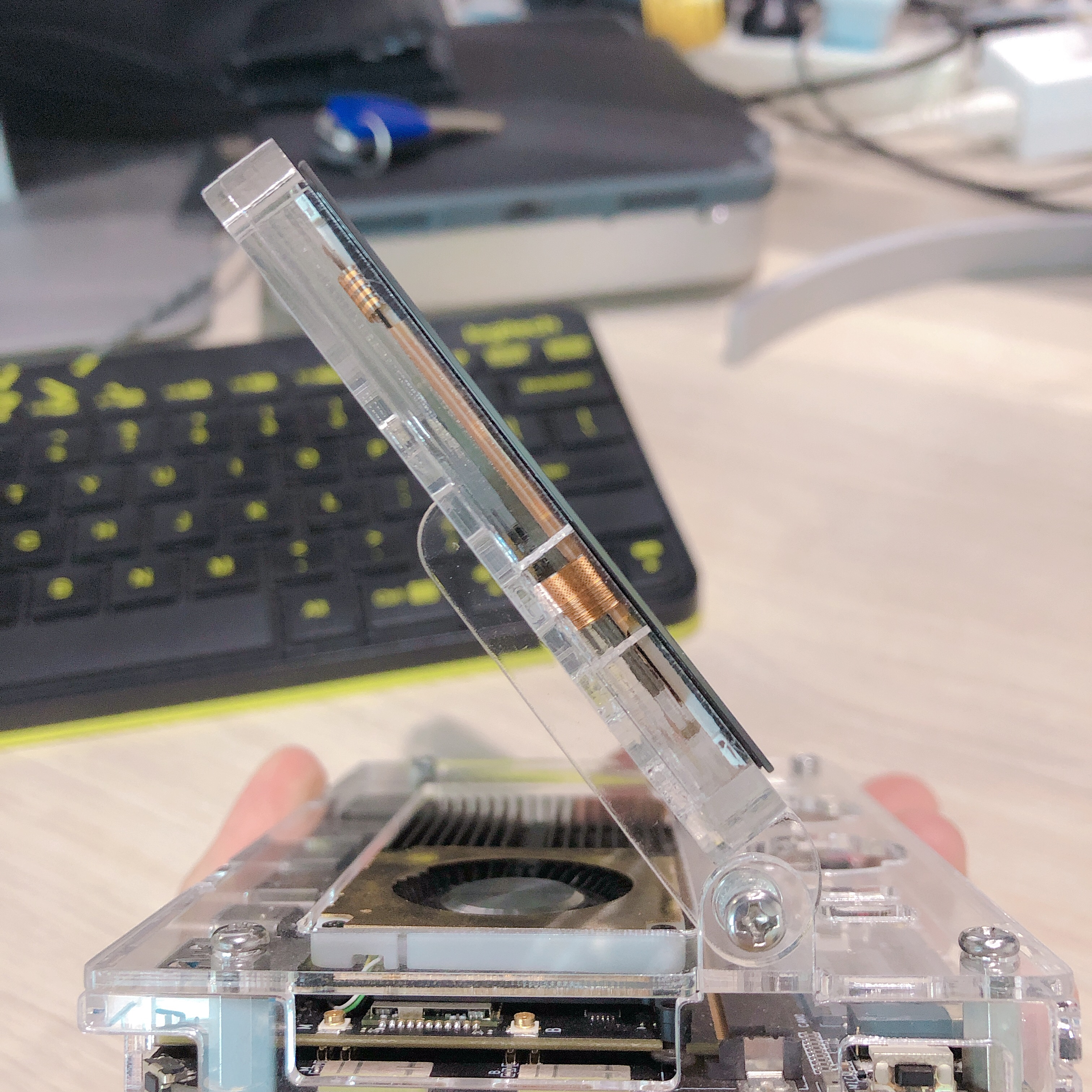
Any suggestions for how to make a DIY “laptop hinge”?
probably your best bet would be to repurpose laptop hinges those are quality and pretty cheap.
But if you wanted a DIY approach just need for it to have a bit of friction and not slam shut not too sure how to do that, despite all the laptops I’ve dissected never tore apart the hinges in particular.
Some sort of blind nut placed from the inside of the hinge. I would be concerned about over-tightening with metal fasteners, specially when using that for friction to hold the display at angle. A spring-loaded, indexed hinge might be better than friction fit, though not necessarily practical.
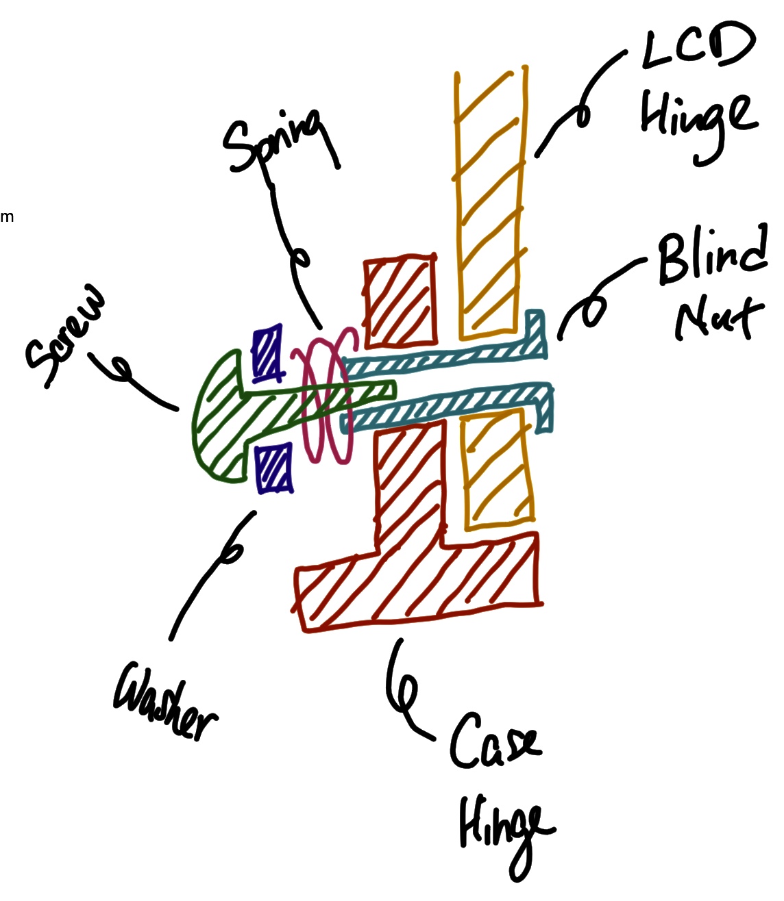
For the sake of simplicity, maybe it would work without the indexing. I would try a blind nut(assuming one can be had at this scale) long enough to extend through, just short of, both hinge holes, a spring and washer under the bolt’s head. The blind nut would also serve as the hinge’s axle. The spring may help prevent over-tightening.
Examples of blind nuts…
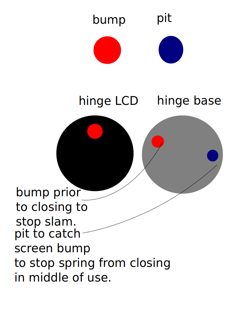
That could work well. But I would imagine either friction or another arresting force would be needed to protect the LCD screen can’t imagine a clap shut approach would be healthy for the screen, probable go the spring loaded hinge approach and have a pit and two bumps on the individual hinges to keep them on their desired position the bump would get caught in the pit when open so as not close itself and when you close it the bump hits the bump prior to closing to slow it down just enough that the back of the screen doesn’t slam on the back of the case.
Oooh that’s a pretty good solution 
Yes you are right, currently all the pressure and stress is on the acrylic pieces.
A blind nut (assuming I can find one small enough), would fit into the clearance hole, and support both pieces of acrylic. A tiny spring should provide the necessary force to prevent the screen from slamming shut.
@Anubis not too sure what you mean, perhaps a drawing would be useful?
I agree with spring placement, as long as the spring does not remove plastic by scraping… Closed coil(example, retractable ball point pen spring’s ends) at the plastic end probably do it.
Yes the bump and pit is similar to what I mean by indexing… Bumps settle in to pits to resist motion. Spring allows for the flex so bump can ride out of pit on rotation.
I was thinking, with acrylic sheet, adding pits would mean boring them in the acrylic. The bump would have to be added somehow. Could drive up costs to produce. If pieces were molded, it might be more practical to add the pits and bump, but this case is acrylic sheet.
Should I end up with this case, I will attempt to index at least 3 positions. Might be more practical as a DIY.
That’s a very clear explanation, thank you
Spring is probably doable, the bumps, not too sure.
Yes, I expounded on my explanation, citing impractical to index the sheet. Specially at this scale.
I have had no luck finding M2 blind nuts. Saw some M3.
If M2 blind nut cannot be found, maybe just a bolt/screw that is not threaded all the way to the head, leaving a smooth shaft to serve as axle. Spring should serve same purpose.
Once the tension on the spring is set, the nut could be secured with a small dab of non-permanent thread-locker, like Loctite. Not sure if thread lockers threaten plastic/acrylic, so good idea to be neat with its application. Nyloc type lock nut could also be used, if they can be found in M2.
A way to lean the screen and hold in place will be required for sure.
How about drop down/fold out leg/legs at the back of the screen cover to help support the LCD frame.
Either a wide one in the middle or 2 small on the edge of frame.
Notches for this leg/legs could be incorporated in case to lock and hold into place,
When titled it would hold firm and hinge is not bearing all the force/weight.
You could then possibly use a less complicated hinge design.
As soon as the screen is tilted up, leg will drop find a Notch, and you can adjust to required viewing angle with other notches.
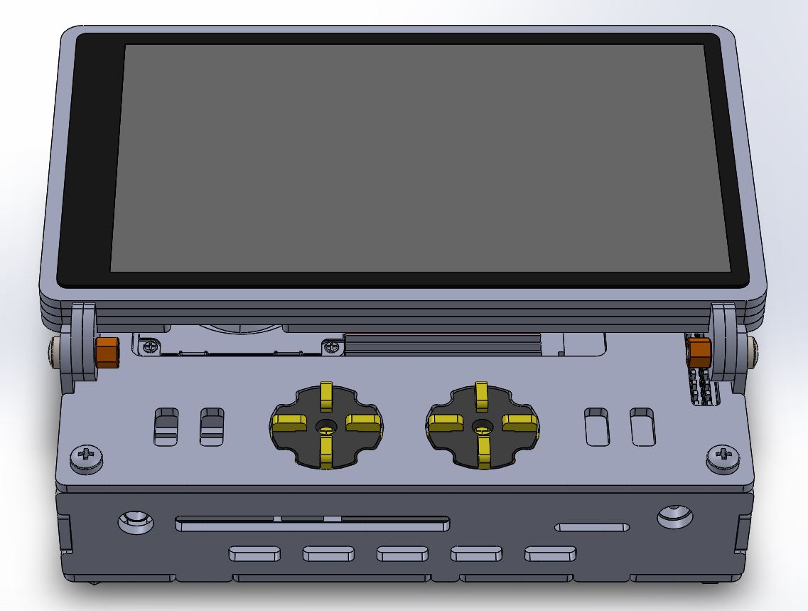
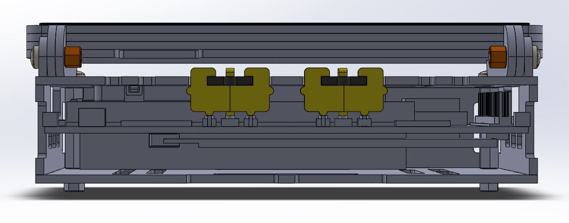
Latest prototype, the buttons are too flimsy, some tolerances are too tight, and others too loose. I think we will keep assembly simple and do away with the buttons.
The buttons were also poorly assembled, and the lower casing is wider by 4mm on purpose.
One of our engineers said: “It’s a beautiful case, but the buttons are terrible. Maybe we should have a daughter board with more widely-spaced buttons mounted on top of the case.”
Our supplier said (rough translation from chinese): “Those buttons are really too small to glue together. If you’re going to make thousands of those little things, the workers will curse you to death!”
Options:
(1) Wide cut-out as per previous prototypes for the buttons, requires a narrower lower case; some adjustment to maintain plastic strength is necessary.
(2) Mount a (new) daughter board with widely spaced buttons on case top, maintain current lower case width.
The LCD is actually really lightweight. I think dropdown legs are only necessary on something 10 inches or larger.
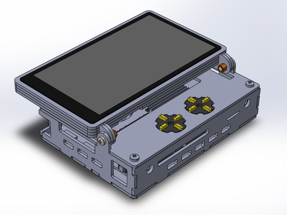
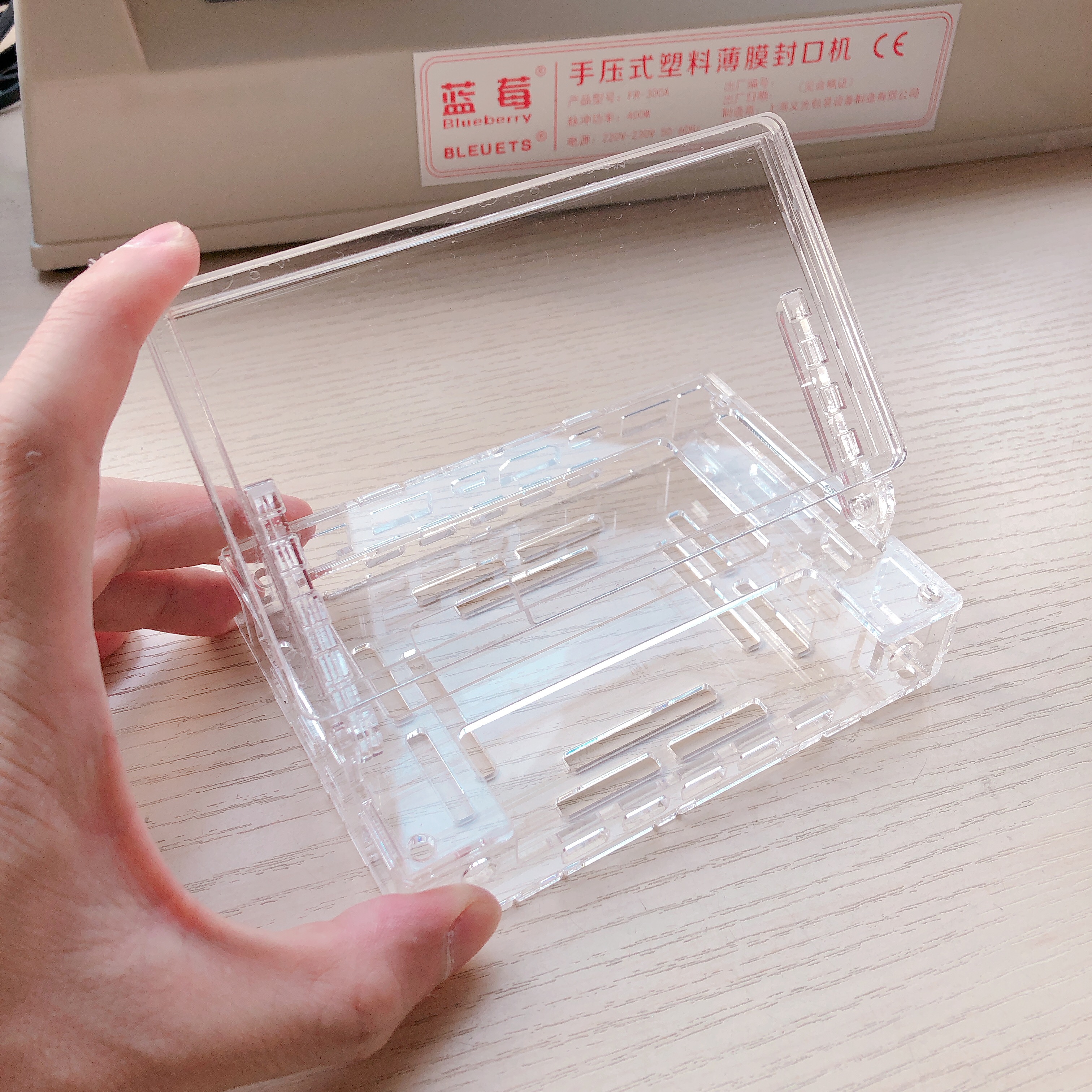
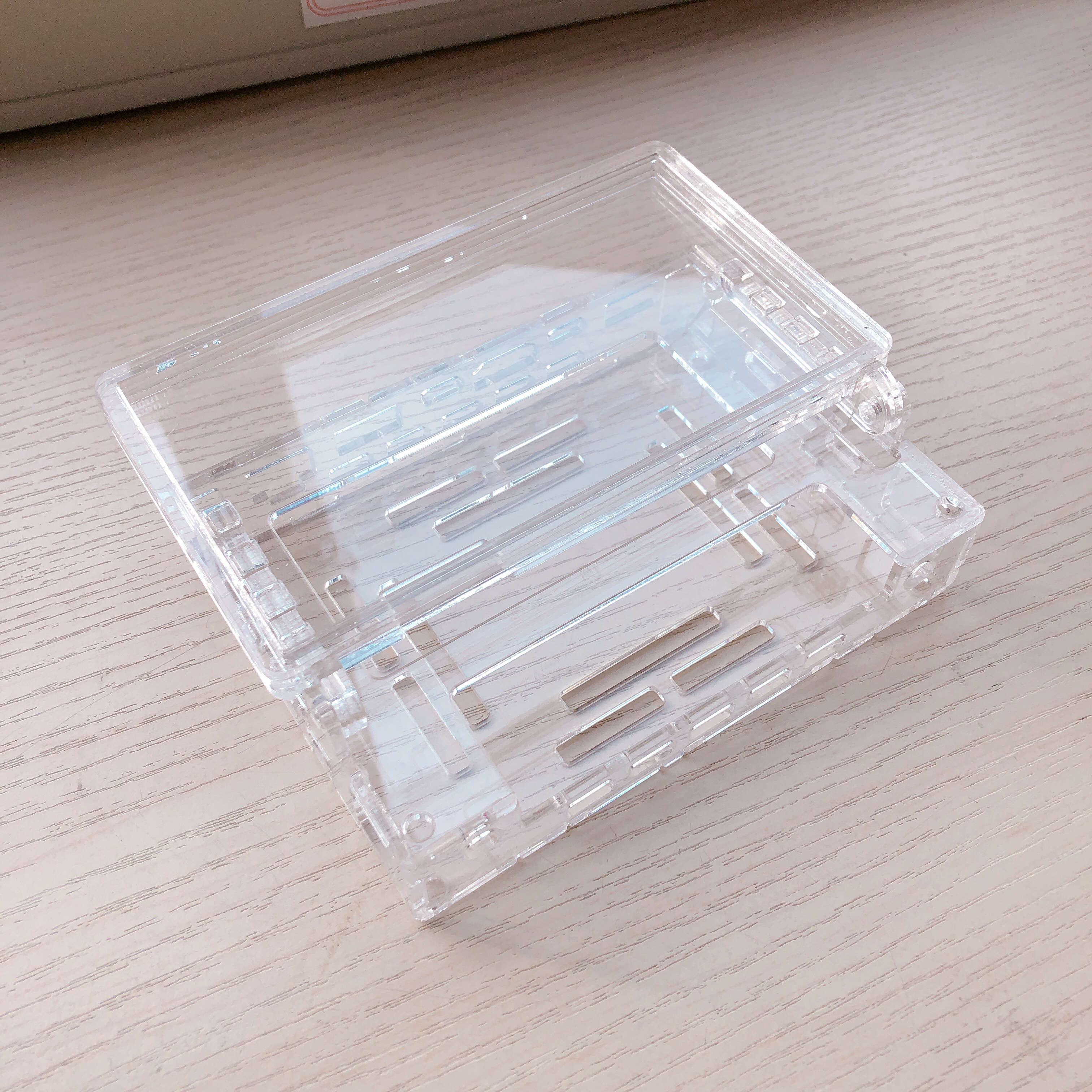
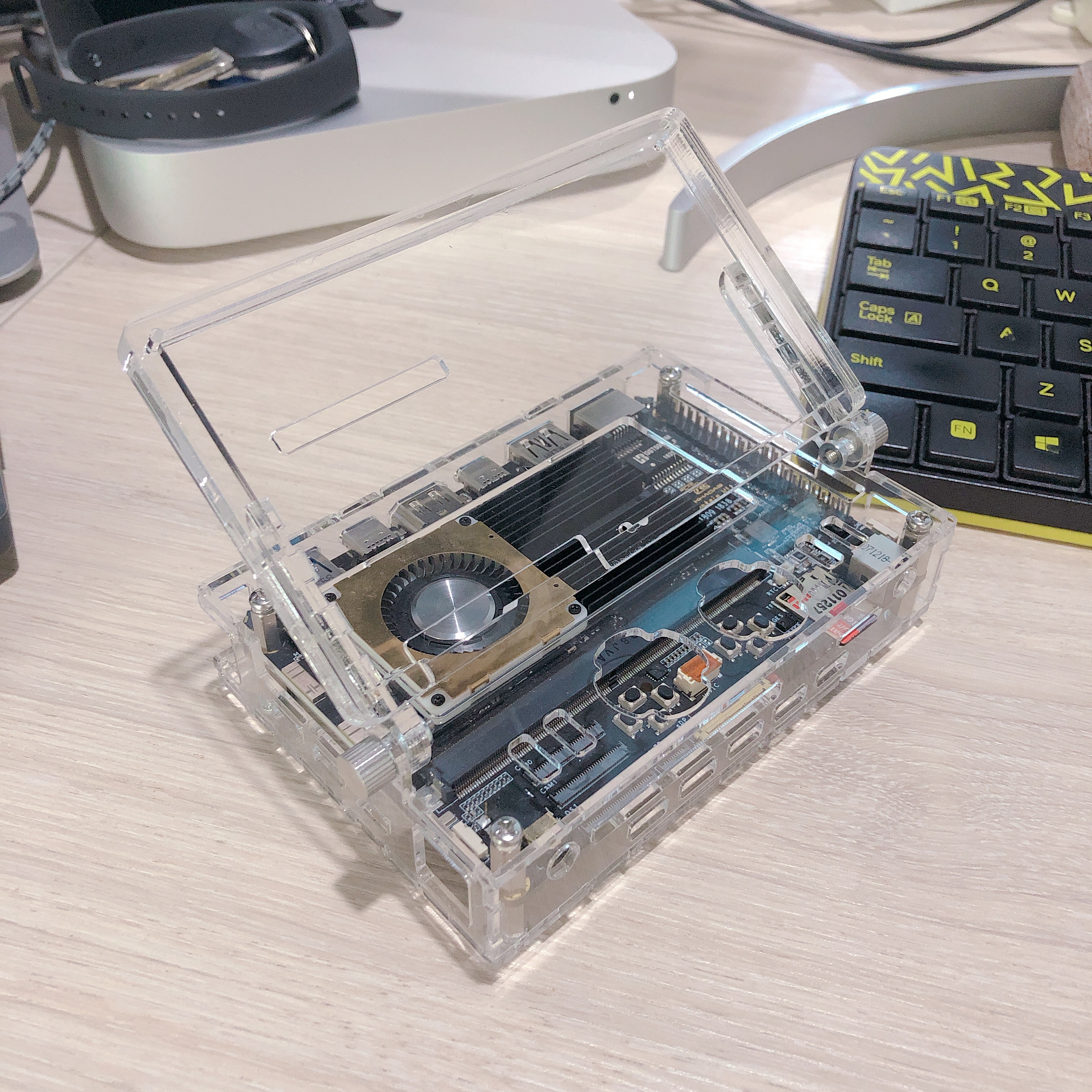
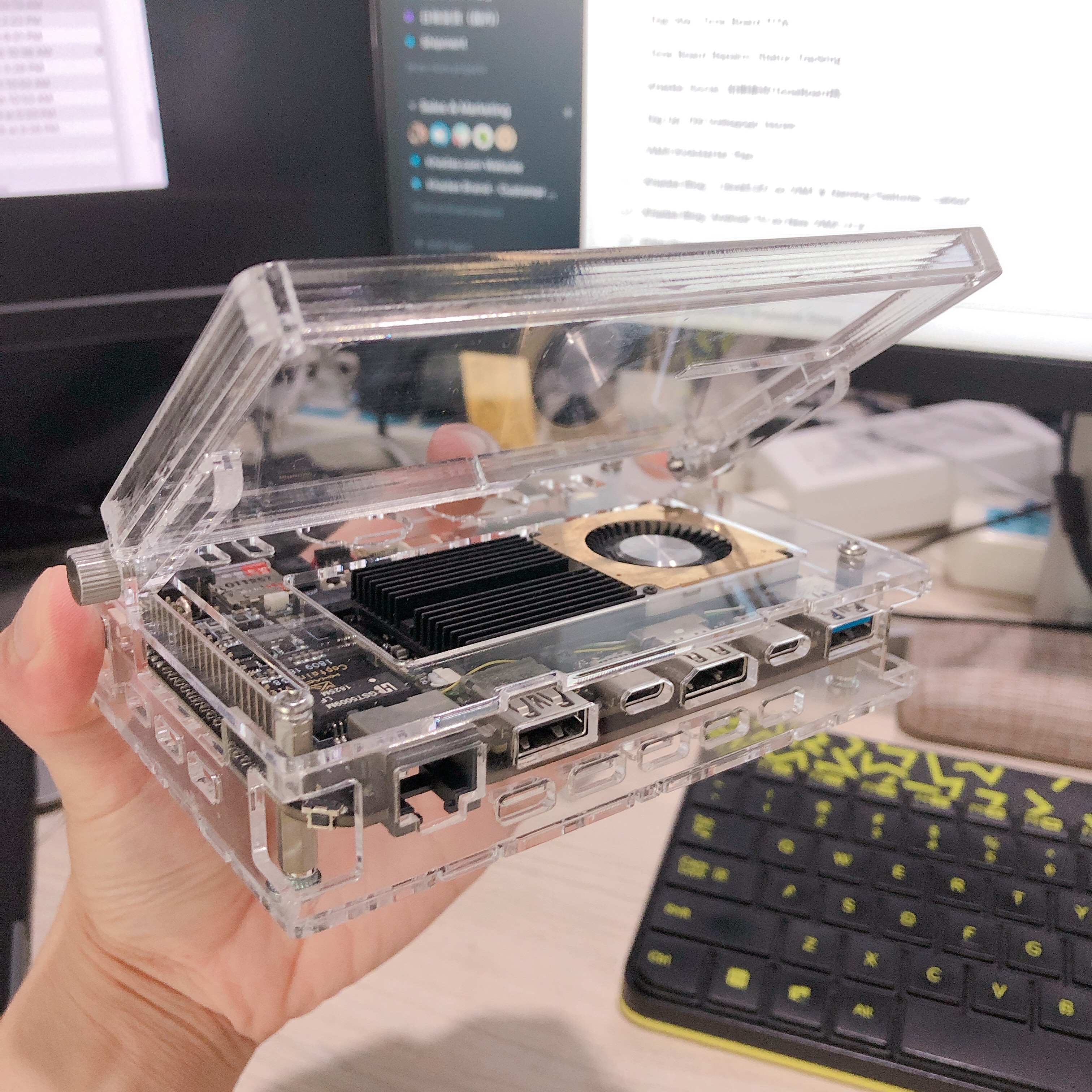
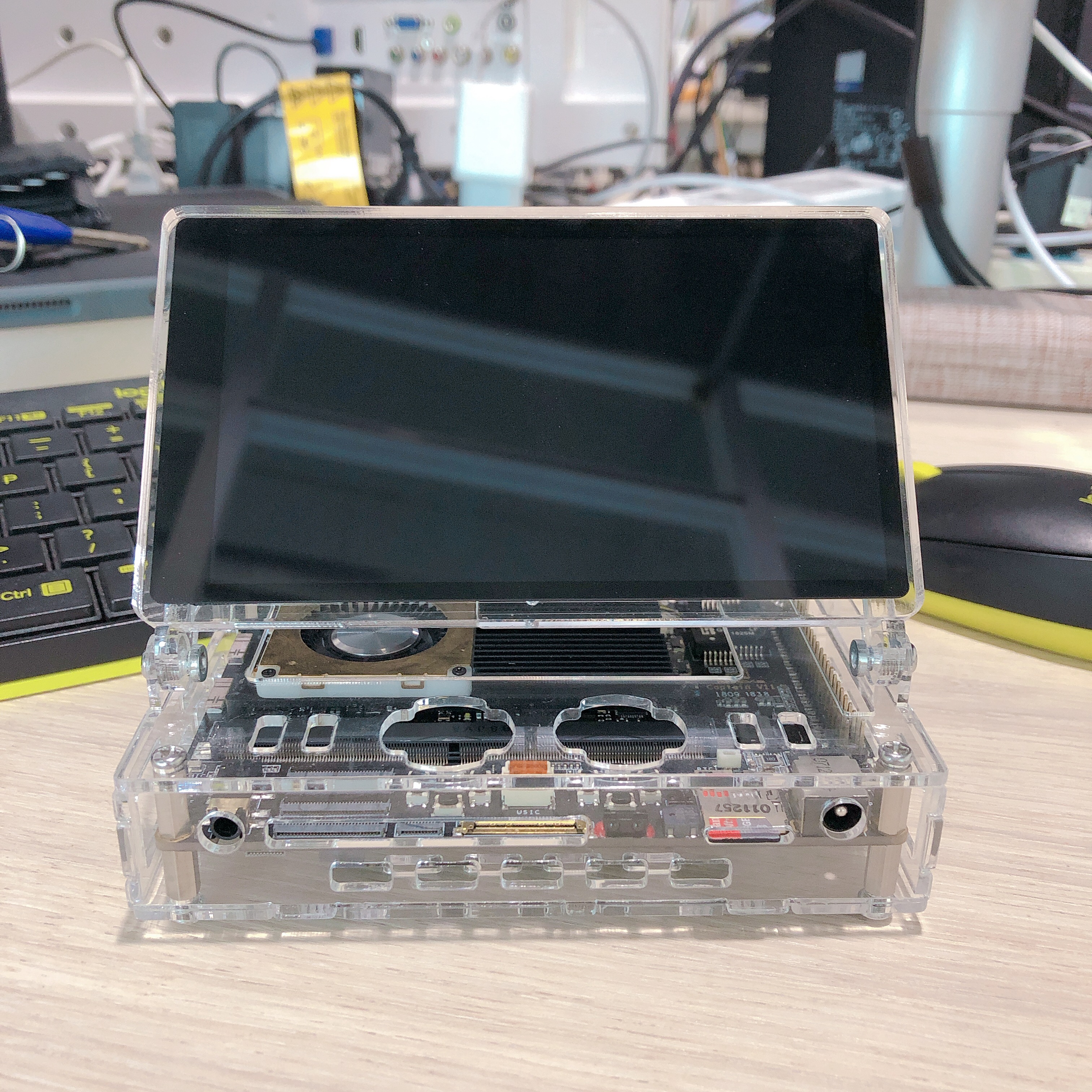
Looks like a real mini-computer now. Just a few things:
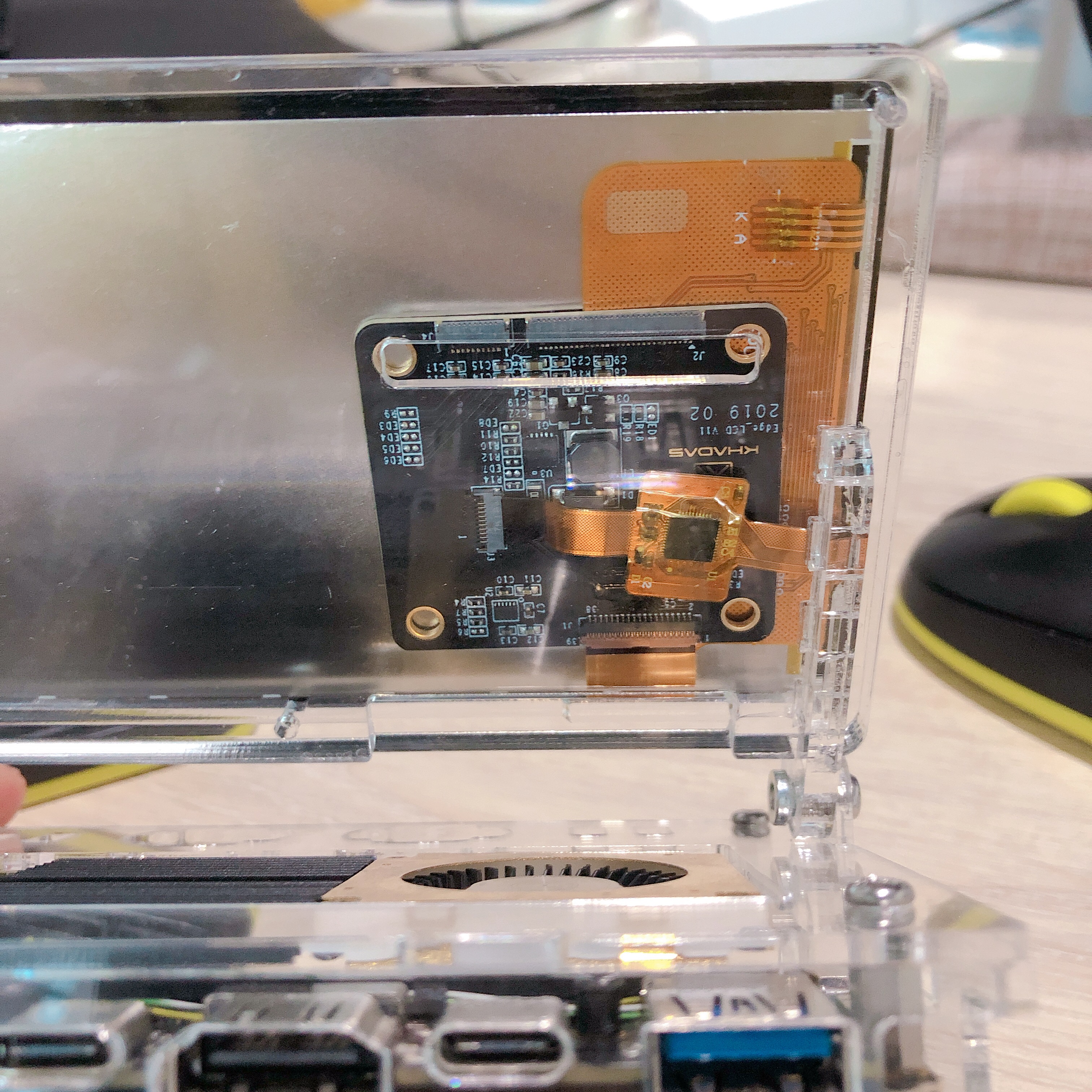
If you forget to attach the FPC cables before glueing the LCD panel into its frame, you’re done. I will cut a wider “thumb slot” into the frame to make it more forgiving.
I’m thinking of having the captain slot into the case from the bottom, since once you locktite the LCD frame in place, you can’t open the device from the top anymore. So only disassembly from
the bottom, like a clamshell laptop is possible.
Disassembly from the bottom will make swapping the battery and SSD much quicker, once fully assembled.
Maybe installing something like Lakka or LibreELEC to run some retro games would be the objective.
Yes I was thinking Bigger for us fella's with failing eyesight and gorilla fingers :slight_smile: