I’m designing an rotating LCD touchscreen mount for the Khadas Captain. Any feedback would be appreciated.
Design is based on the assumption that we’ll use acrylic sheets, M3 standoffs and screws. If you guys have more suggestions for fasteners, components, etc, would be helpful.
V model could mount as is nearly
Standoffs made on a frame to match mounting holes on Edge V
Edge V could be mounted in corner
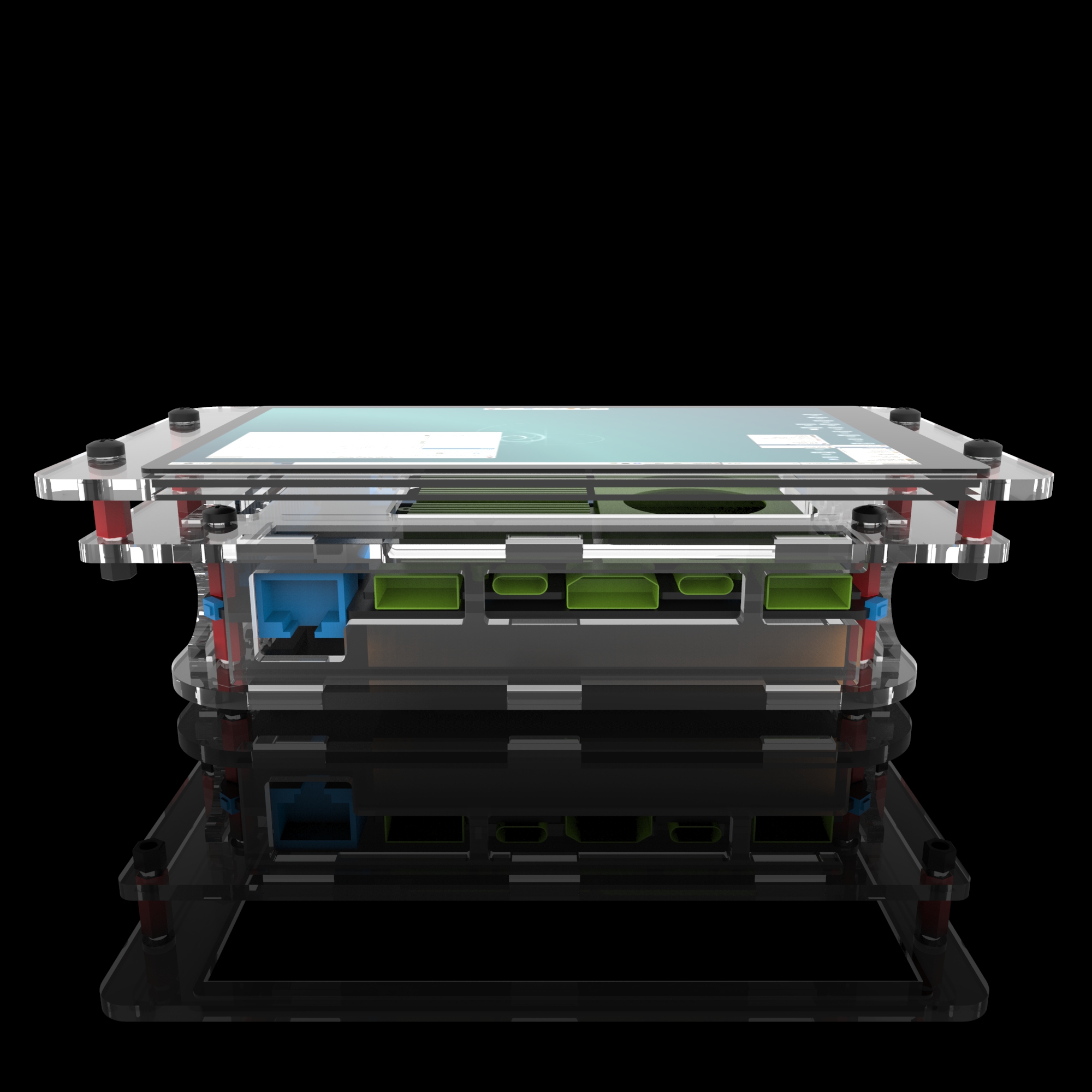
Ports could be accessed (cut out in bottom edge)
Switches thru side. ether buttons or just pin holes
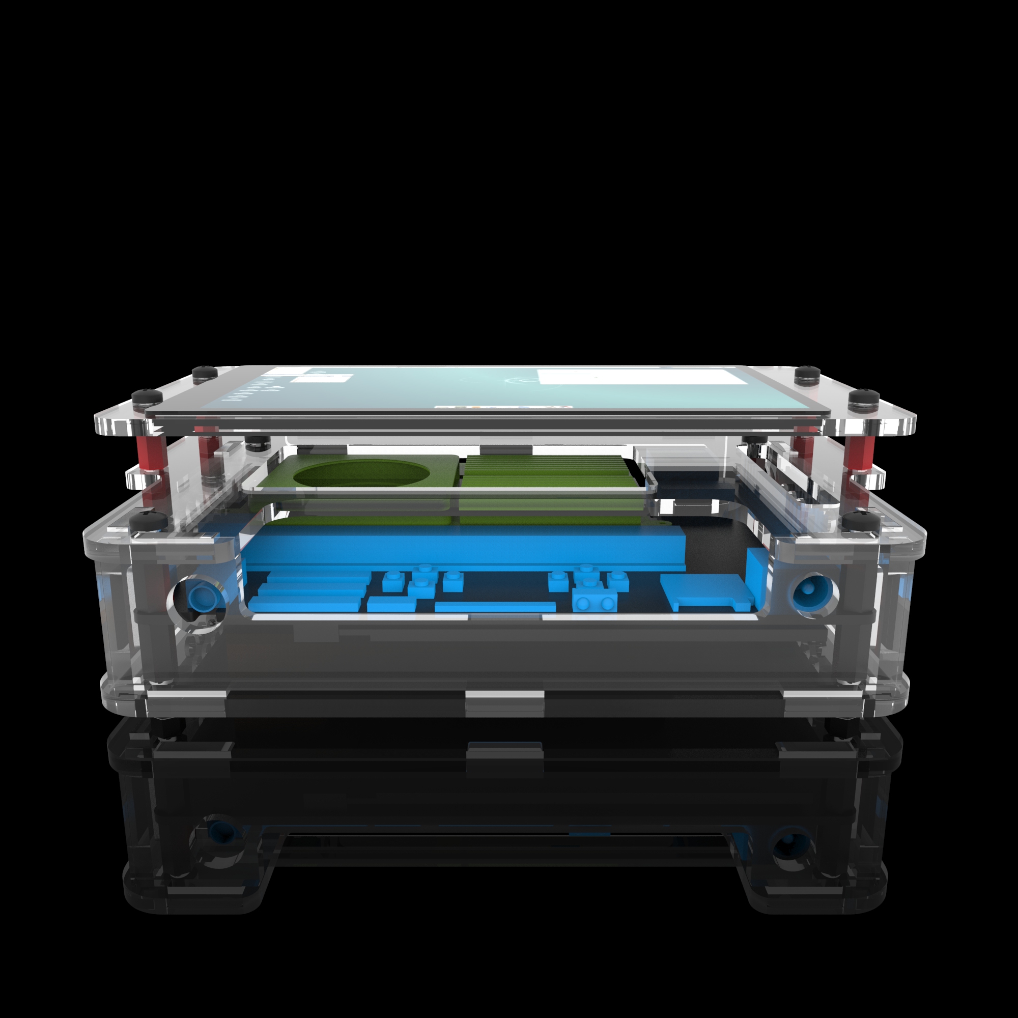
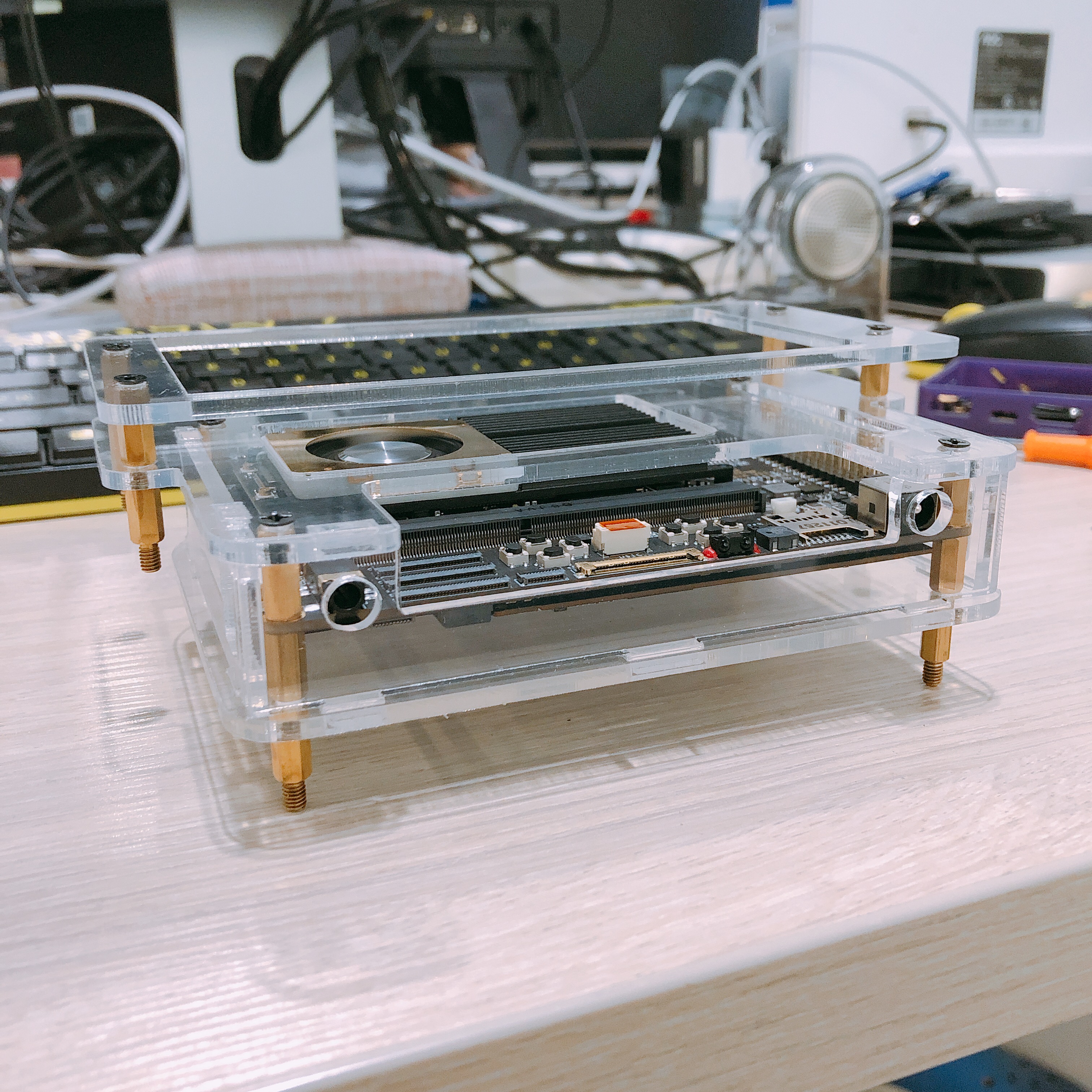
Captain have no Base on back so you could access all buttons and bits required
A clear case would set if off look kinda groovy, or metal, again all in the tooling
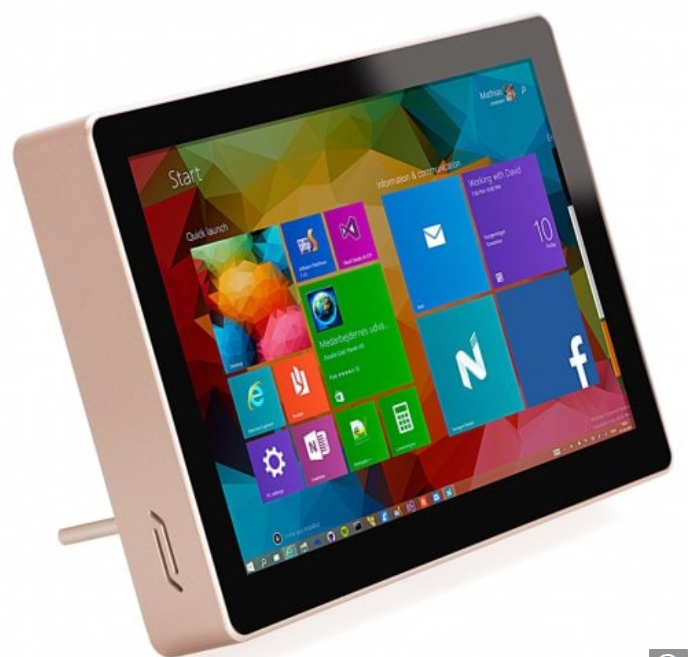
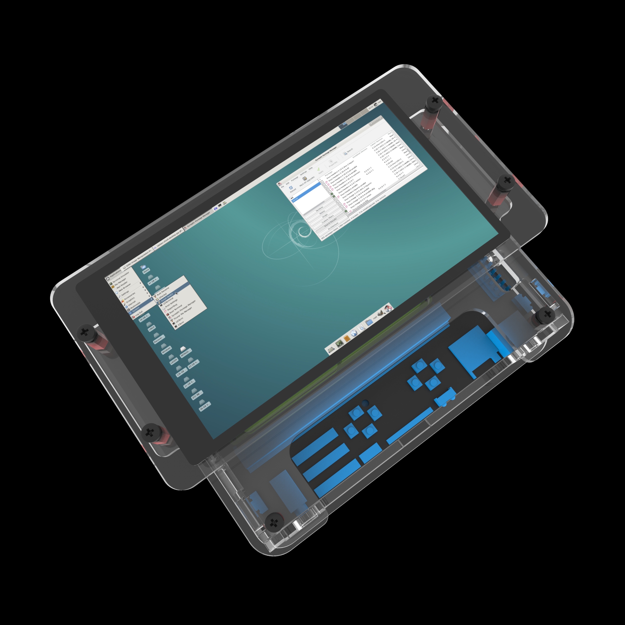
7 or 10 inch version possible just a bezel on front to cover dead area
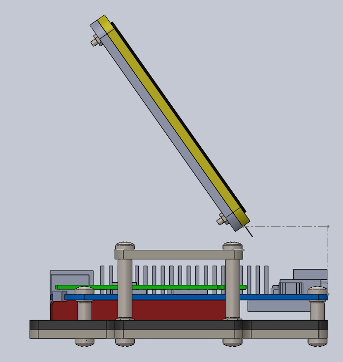
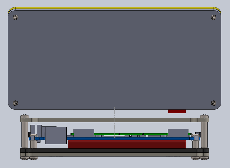
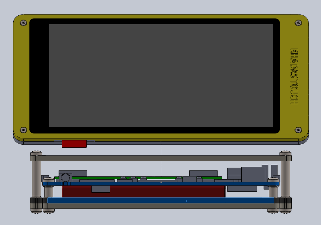
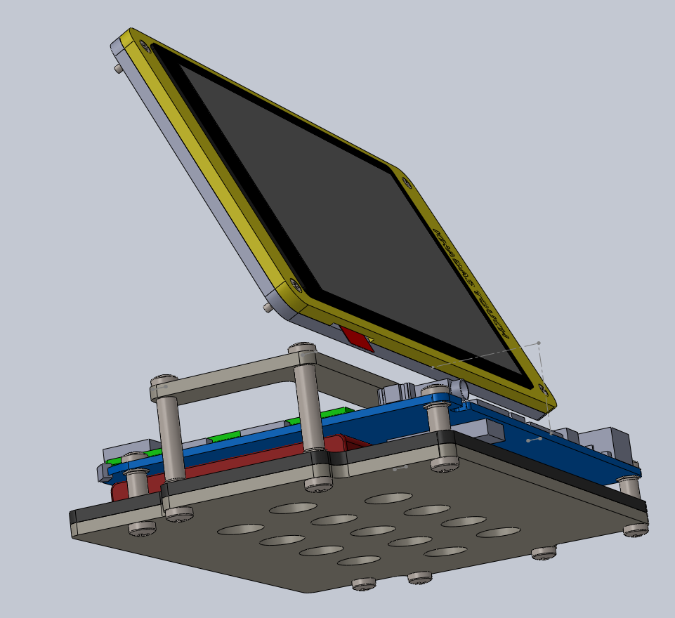
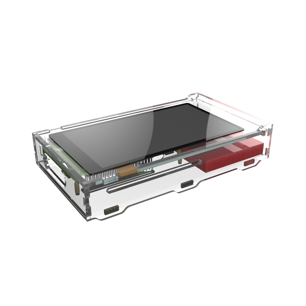
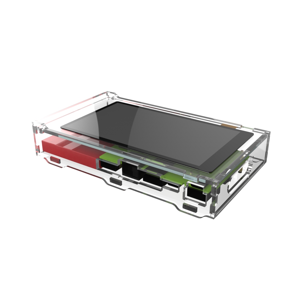
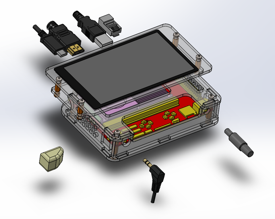
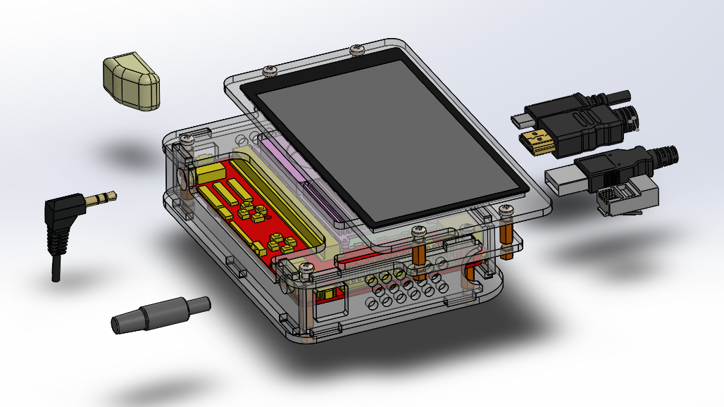
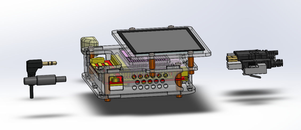
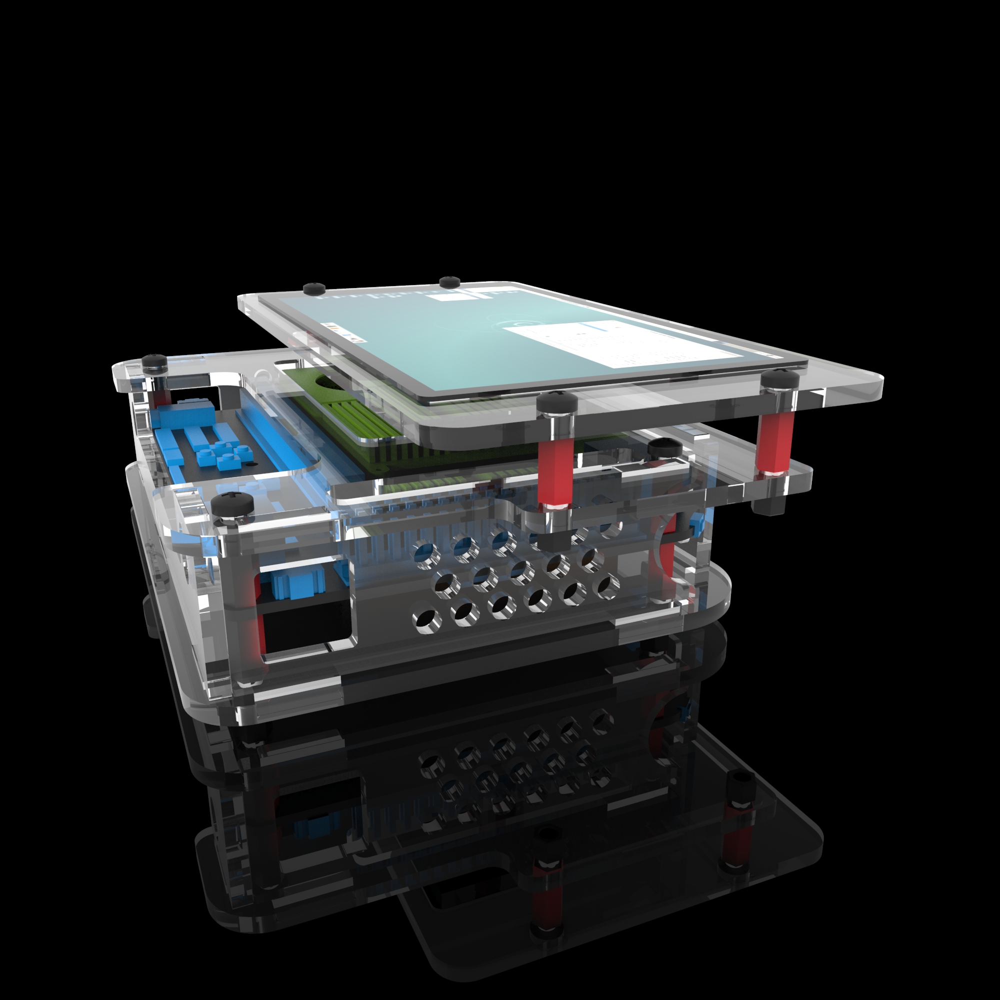
Tablet form-factor for Edge-V and 1080P Touchscreen. (Also compatible with Li-Po Battery, New VIM Heatsink and 3705 Cooling Fan). Design is subject to change, as this is a concept only.
Added some renders for consideration. Potentially some issues:
(1) LCD’s eDP and TP cables may block the left game-pad buttons.
(2) Rear acrylic cover may be brittle, even at 3mm, due to thin walls
(3) Accessing GPIO would require user to unscrew the LCD mount (change to magnetic mount?)
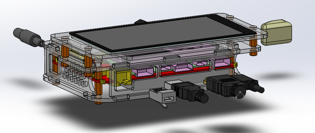
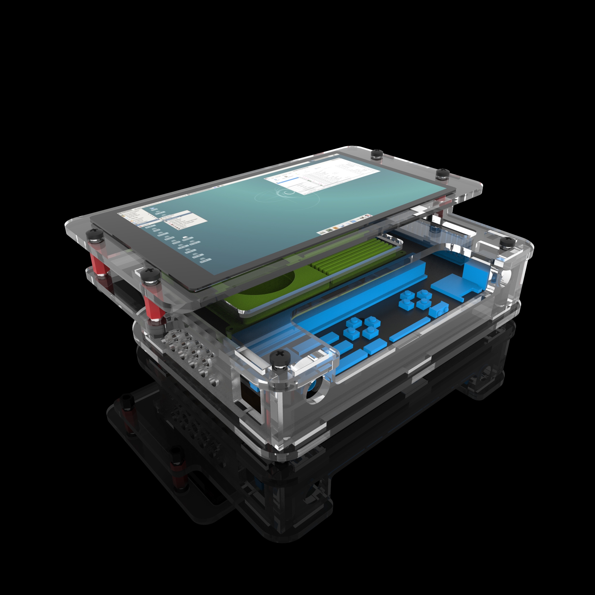
I figure the shoulder buttons on the captain would get in the way of most builds and limit the form factor. So a suggestion on the next iteration on the carrier board would be to add horizontal facing PWM pins having them configurable so users could use wires to lengthen the buttons or use other input devices like flex sensor, potentiometer or light sensor or not bother using them altogether.
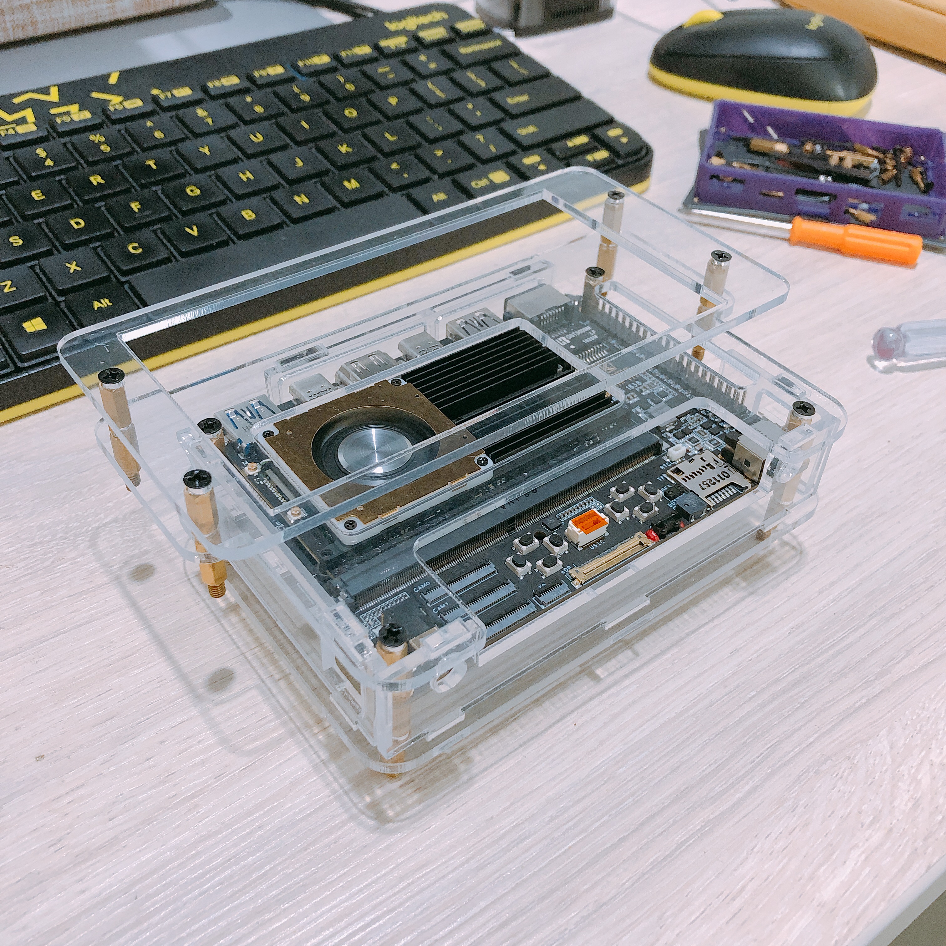
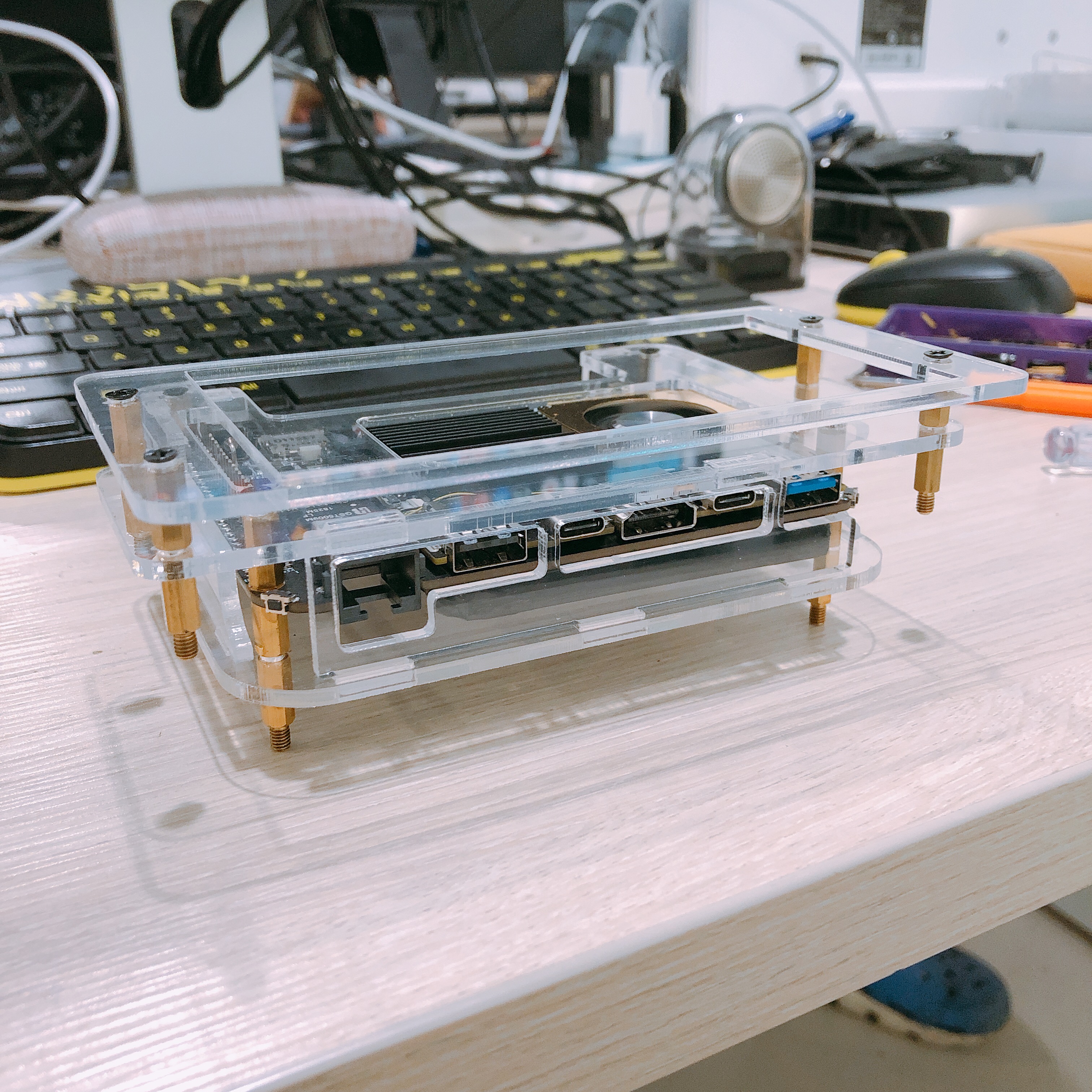
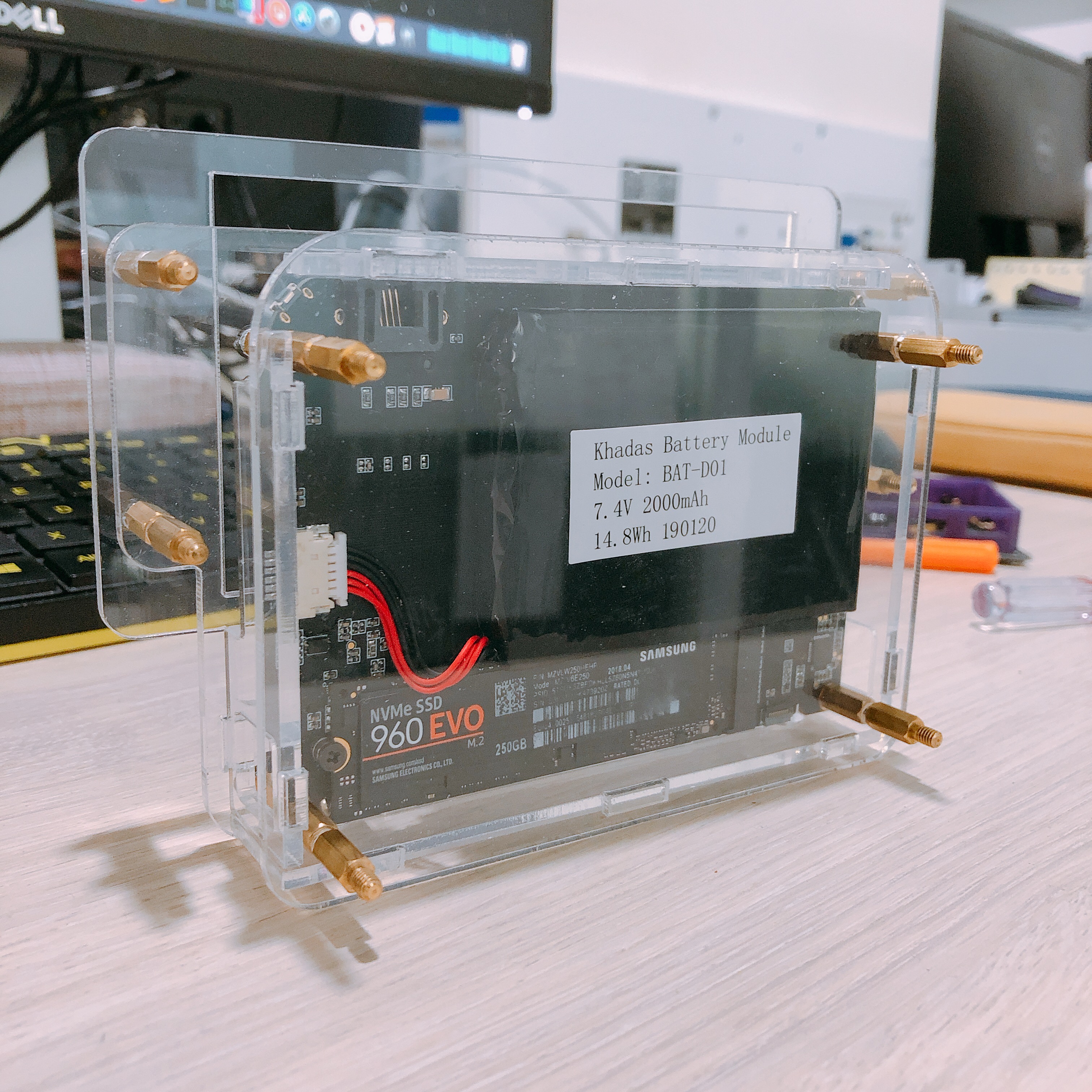
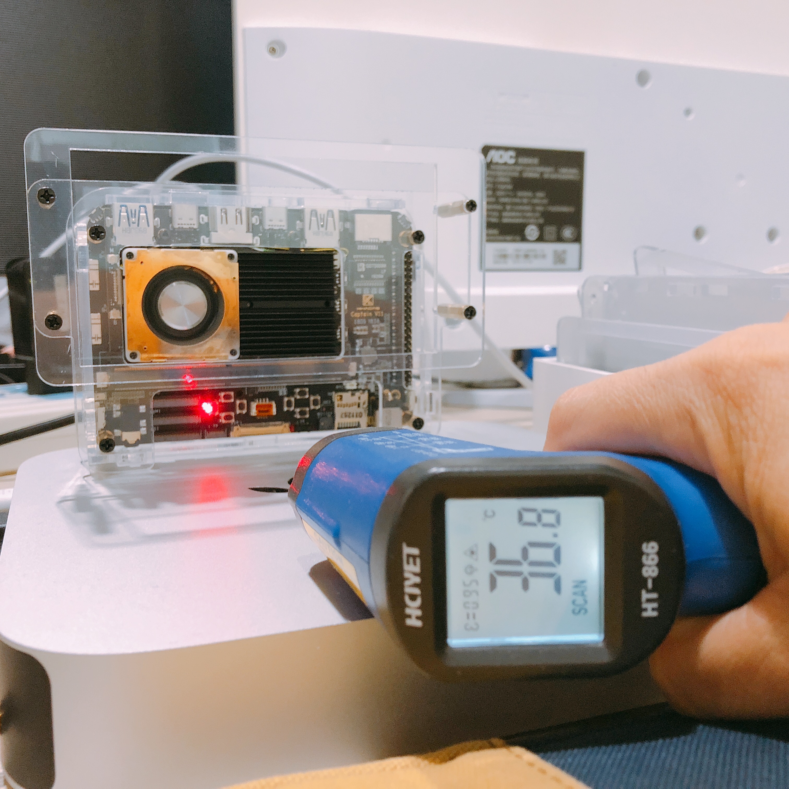
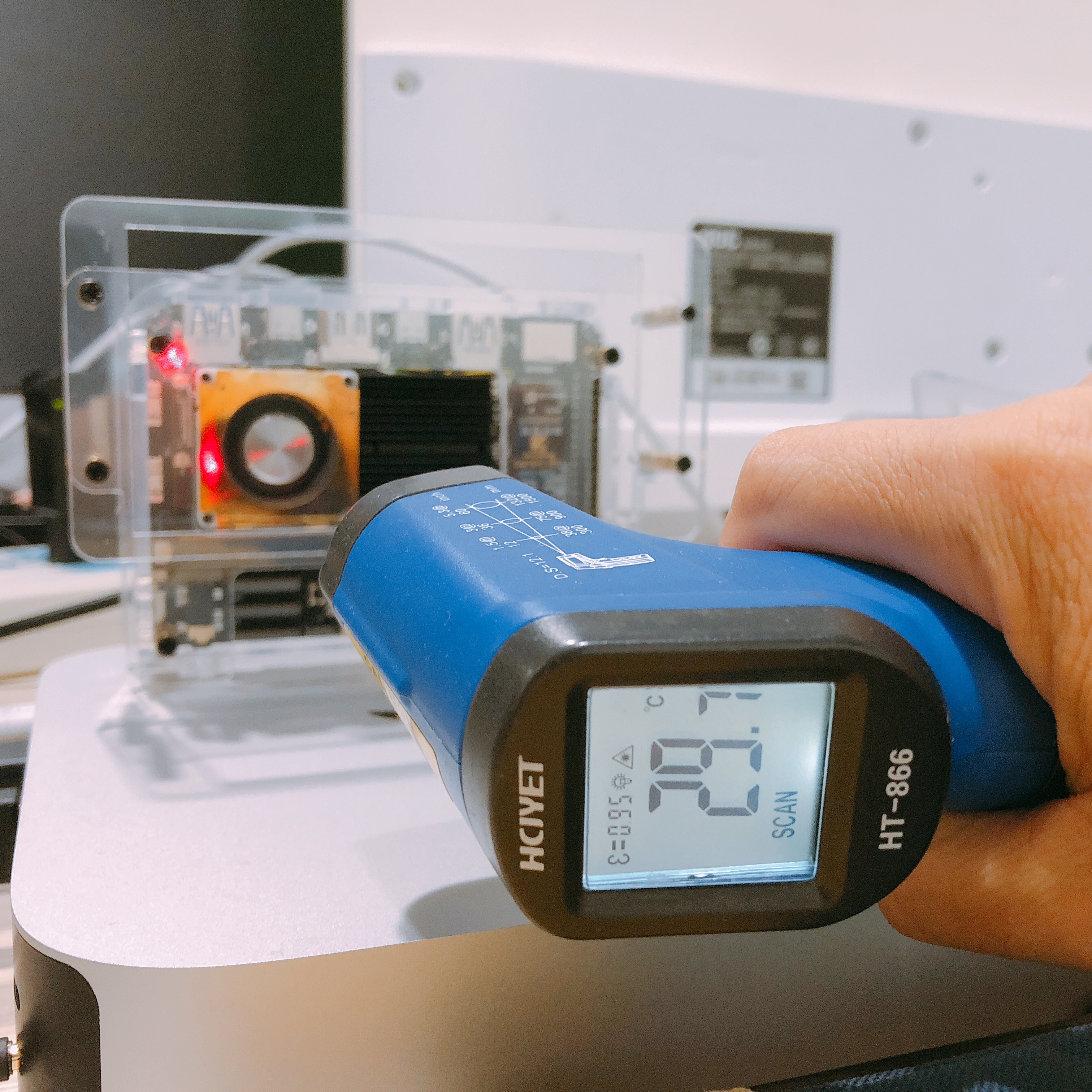
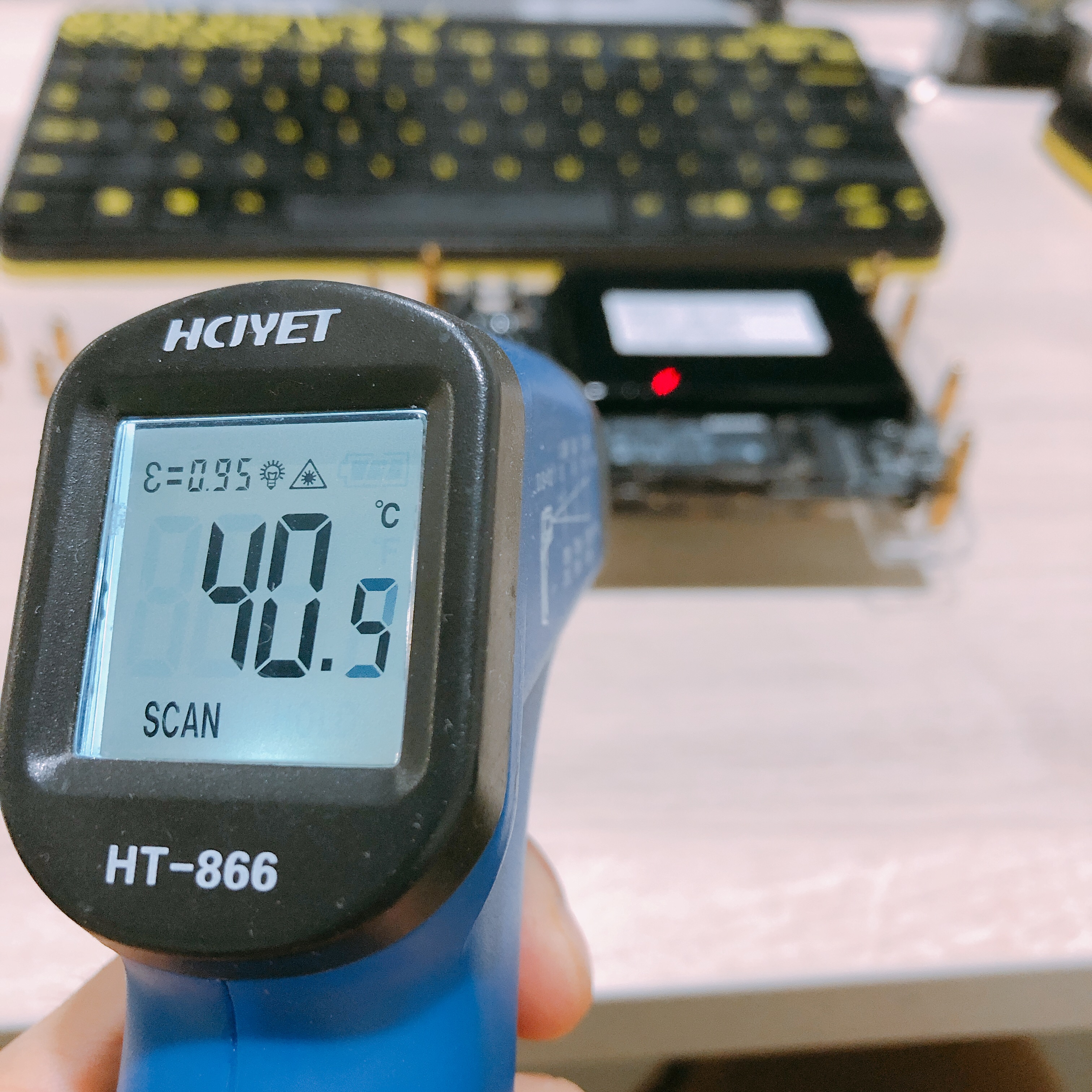
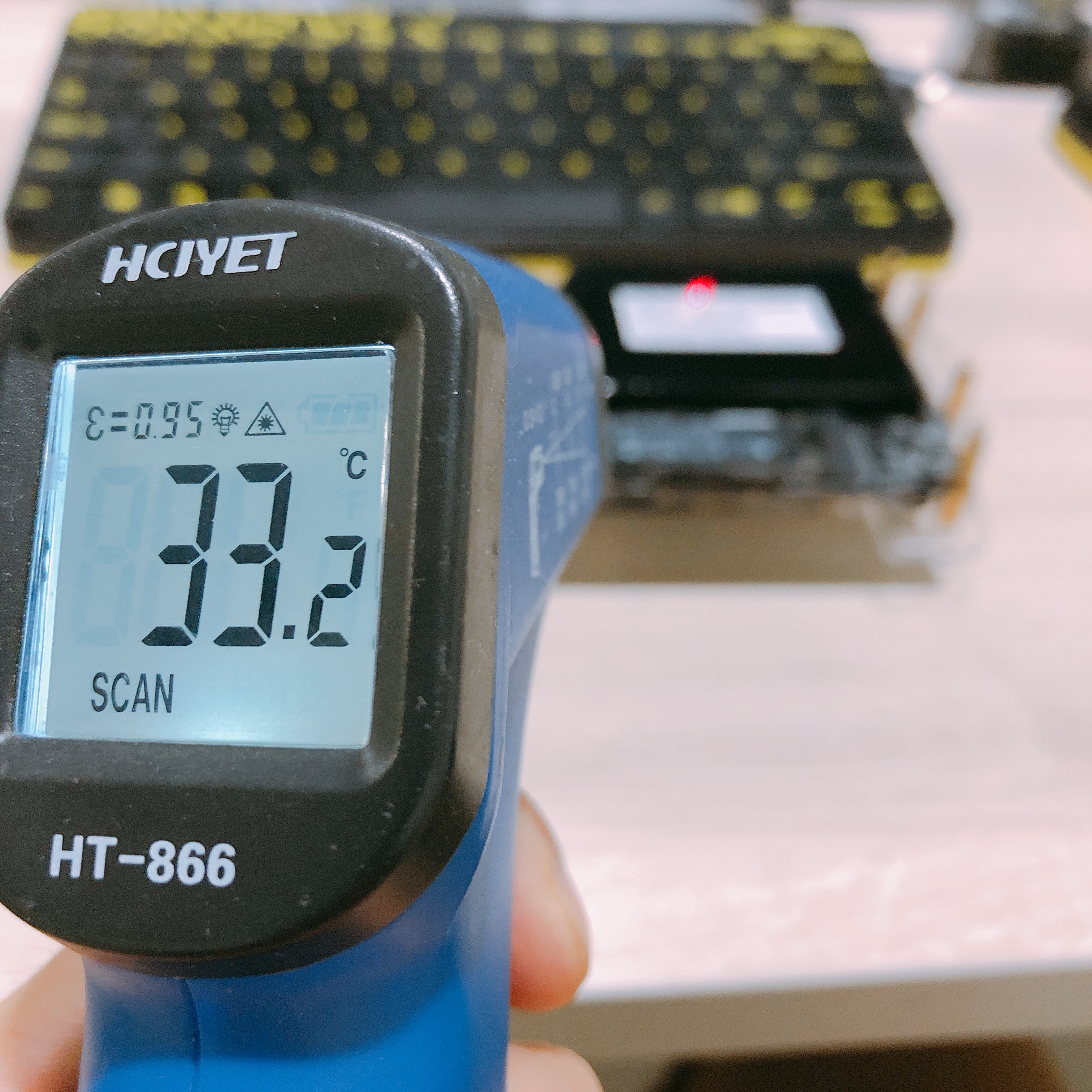
The SSD however produces a lot of heat, even while idle. It’s almost at 40C just doing nothing, and warming up the top-deck to 37C. I think it needs its own fan and heatsink, haha. Ambient is about 29-30C.
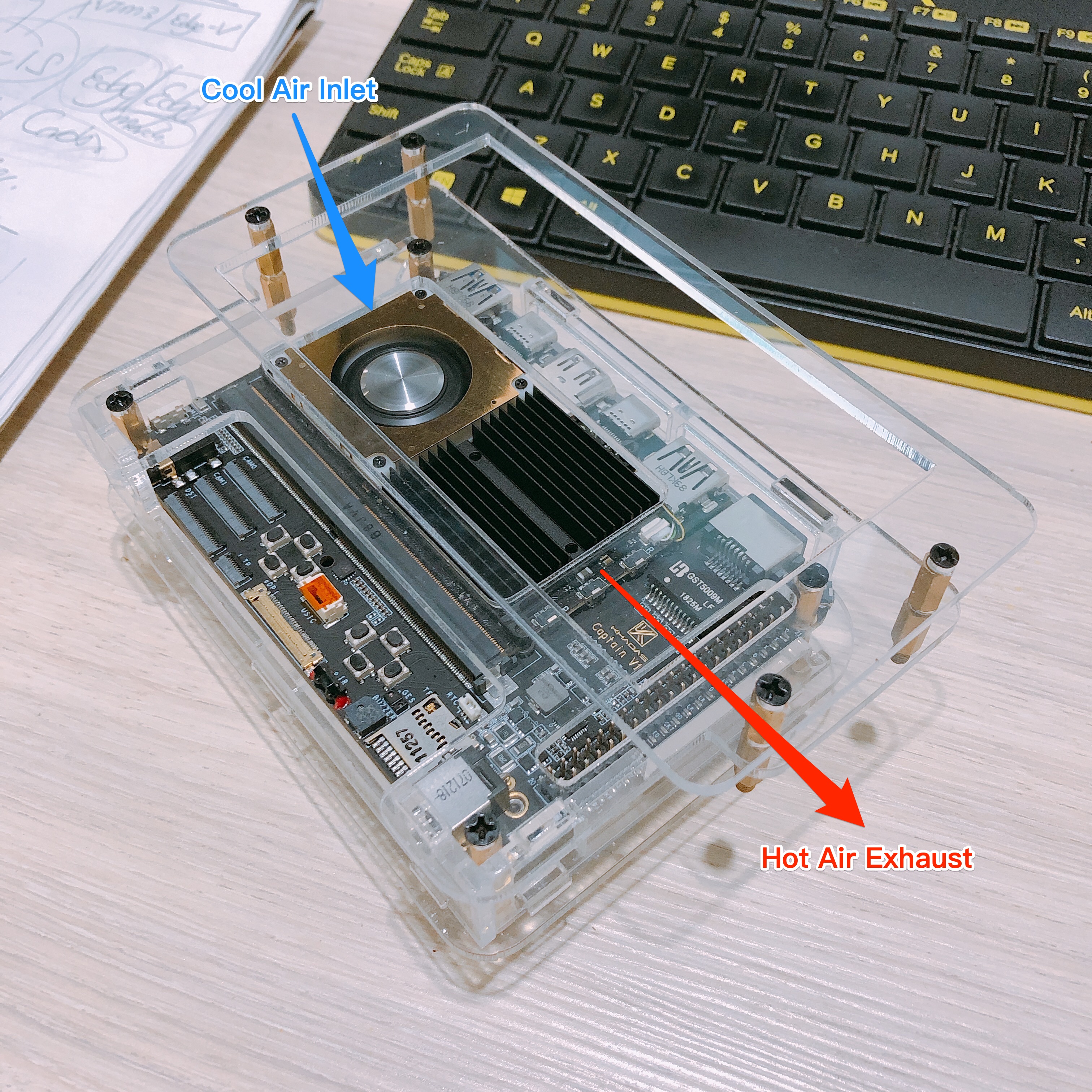
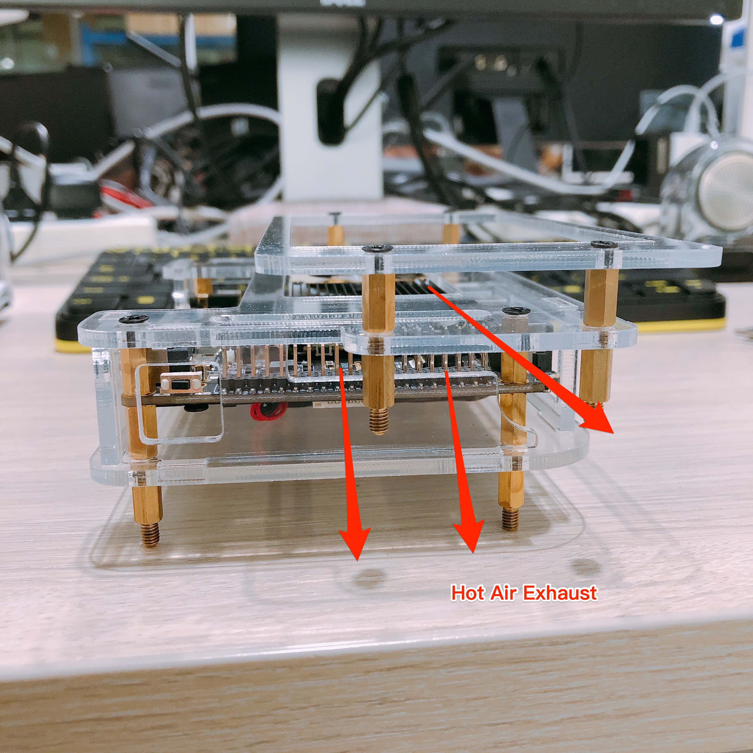
Another problem you might run into with the carrier board is the gpio placement as judging by the air output annotations in the above picture if you utilize the gpio pins you’ll end up blowing hot air against the connectors and that would really diminish the heat dissipation of the heatsink. maybe on the heatsink swap positions of the radiator fins and the fan as the left side of the carrier board looks largely unused.
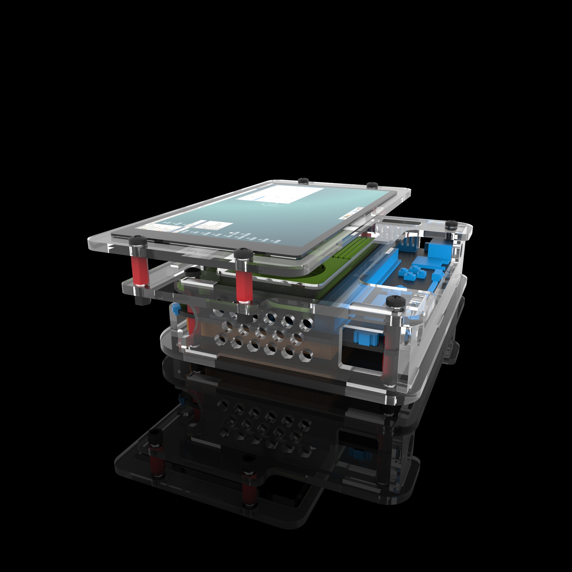
That’s a good point. However we’re unable to swap the heatsink fin position as our goal is to make it compatible with the DIY Case. When I have time I’ll run another CFD to compare airflow when the pins are obstructed. Thanks @Anubis!
wow I’m suprised it actually looks cooler, might want to include some fake gpio plug for the people that want the reduction in heat without actually using the gpio headers.
Never mind thought those were thremal readings. If you decide to make a sleek case for the carrier, LCD, battery, and edge combo(I would love a DIY tablet) might add an outlet manifold leading to the top so the hot air isn’t recirculating and gpio headers can be utilized, two wins zero compromise.
Good idea! I’ll add a little shaped-plug for the GPIO and modify the acrylic case a little, and see how that goes. Perhaps getting the air to leave from beneath the LCD panel could be the better solution, rather than allowing it to pass through the GPIO pins.
That said, there’s still the issue of the hot-SSD though. Of course if you didn’t install the SSD it will be fine, haha!
no problem, that looks much better with a cleaner exit. By the way any idea if my suggestion regarding the carrier board shoulder buttons being swapped for pwm pins will make the cut? they would be useful for anyone wanting to utilize the shoulder triggers for anything larger than a tablet, aside from that would allow usage of external sensors or inputs.
regarding the SSD if your referring to the nvme maybe include an adhesive heatsink that attaches to the ssd or a metal back plate for for the case that conducts heat from it.