Water Auto Turret - Khadas Community Competition Entry

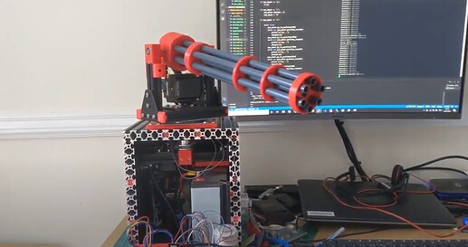
Thought I would share some progress on my new project - decided i should use at least one of my VIM3 for something other than crypto mining and its heading towards summer so thought i would make a water auto turret for my daughter for fun in the garden this year! Connects to a standard hosepipe fitting and runs on a 12v battery so nice an portable as well!

Electronics and mechanics are mostly done so thought i would share a video of its first movements I’ve got it to take this morning! Im using TMC5160 motion controllers so positioning is easy and now done (~-1350 to ~+1350 in yaw show in video). Now I just need to get the object tracking with yolo working (might need some help here thinking of using ctypes to wrap it so i can access from python - but at least i know who to tag now - thanks @tsangyoujun !) extract the positions from the frames and translate that to yaw and pitch to get the water in the right place (i.e. on the kids :slight_smile: )

https://photos.app.goo.gl/BgPEzR7aCiydPLMe6

Open source as usual GitHub - neilbirtles/WaterAutoTurret: Auto Tracking Water Turret

Github Pages site also available for this project now Water Auto Turret | WaterAutoTurret

6 Likes

That is innovative, interesting, and totally cool(pun intended).:grin:

2 Likes

Wow! That’s incredible! I’ll be sure to include it in the next community newsletter. :slight_smile:

4 Likes

Quick update on this - now got it all auto homing, a network interface to the khadas NPU example (modified the demo program to output json messages for tracked objects - didnt fancy wrapping it with ctypes and wanted something running fast to test) and rudimentary tracking working. https://photos.app.goo.gl/Ju2jiPrX89tj3P5a8

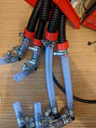
Had a minor issue with the water tubing - thought i better test without the electronics in first - turns out that was a good idea as lots of water leakage from the silicone tubing and cable ties approach i used as it couldnt handle the pressure. All now replaced with PVC braided pipe and hose clips - hopefully that will work better! Just waiting for the epoxy to set on my hose adaptors and will pressure test again.

But now have seen that there is a python api released for the NPU (thank you!) - so glad I didnt get too far down the road of the doing it myself! Now will port over to that and see what progress can be made in the few days i have off work this week. Hopefully lots as now I can have on (multi-threaded) program rather than having to get data between two of them

4 Likes

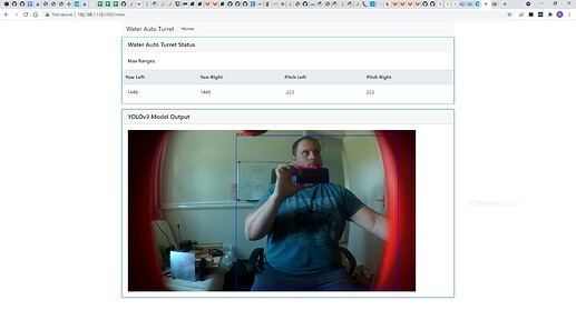
Well the python API for the NPU let me make some easy progress this afternoon - knocked up a web front end to get some feedback on turret status and will expand to make the control method for the turret. In the development phases will set up parameters for easy tweaking to change the targeting sensitivity etc.

3 Likes

A.I: “kill all humans” :rofl:

Good thing you only gave it the ability to shoot water.

3 Likes

Yeah, I did think about this! Will just have to make sure it doesn’t get sentient :joy:

2 Likes

Have been working on this again now as wanted to get it entered into the khadas community competition. Currently working on getting the last of the parts finished and 3D printed then will publish the complete Fusion360 model of the water turret. Just getting all the conflicts that I would have noticed if i had modelled everything sorted like this piece that needed angling off so it clears the pulley for rotating the barrel

Have also been looking at increasing frame rate and multi-object (i.e. children :slight_smile:) tracking so that i can ensure they are all equally soaked, but want to get the mechanics finished and published first before getting back into the software!

2 Likes

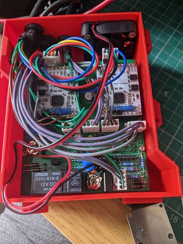
Electronics enclosure finished and wired up (who can spot all the mods on the circuit board :slight_smile: )

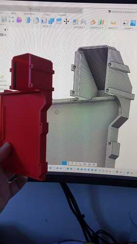
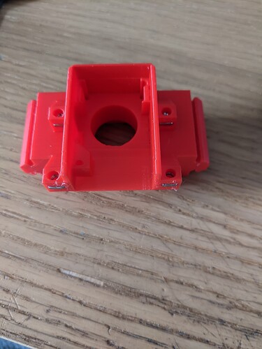
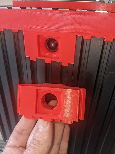
Have modified the camera housing to include a bevel to try and remove the blocks to the camera view you can see in the post above and also to move it down by 1.5mm to allow the top of the case to fit under the metal enclosure. This is an interesting shape to design and print - but made much easier with the khadas provided model for the camera!


Last photo shows the previous (bottom) and current (installed) camera holders

2 Likes

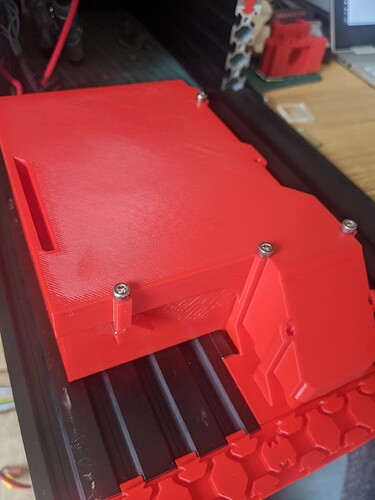
Assembled electronics enclosure with the new sloped top to clear the yaw pulley - fits together pretty nicely. Gap down the right hand side is the air intake - got some baffles in there to try and avoid getting any water sucked in whilst still getting cooling

2 Likes

Wanted a break from coding so after a bit of an STL export marathon I’ve uploaded all the 3D printed parts for the water turret - have spotted that github now has an stl viewer built in so anyone interested can have a look at the parts. Didn’t realise there were quite so many! :joy:

3 Likes

Just pulling the build guide together for the water turret. I’m intending this to be sufficiently detailed to allow anyone to build one of these as its actually pretty straight forward now I’ve got the kinks worked out. All this will end up on github shortly but collating here for the moment, so any feedback on content will be welcomed! Part 1 3D printed parts…

3D Printed Parts

All 3D printed parts were printed from PLA on a Prusa Mk3s, using standard settings. Only those parts that have their names appended with “(Supports Needed)” need supports enabled, all other parts have been designed specifically to be printed support free. All parts have been saved in the correct orientation for printing to simplify the process. As they can be added to your slicer of choice, sliced and printed. The variable layer height feature was used on all the parts to speed up the print time as there are quite a lot of parts to be printed!

On a well setup printer the parts will be of the correct size to fit together, with many of the parts being friction fit into the aluminum profiles and over the plastic tubing the barrel is constructed from. It is however usually worth pushing the parts designed to slot into the aluminum profiles through a spare piece of profile to make sure they are a tight but not unreasonable fit. Where the fit is too tight sliding them in and out of a aluminum profile a few times (with the help of a rubber mallet if needed!) will get them to the perfect fit.

File names for the stl files link back to body names in the Fusion360 model for the water turret so allow for easy identification. The following are the parts that need supports along with a suggested description of where the supports are needed. The Prusa Slicer support painter feature was used to limit the supports to where they were needed to avoid large amounts of unneeded support material that would need to be removed.

  • Electronics Enclosure::00 Electronics Enclosure Base (Supports Needed).stl - supports only needed along the very top side (when orienting the part as saved, and the side that joins to the camera housing), all other areas can be masked off or have maximum 45 degree angles to allow supportless printing

  • Turret Barrel Mount::04 Barrel Microswitch Mount - Front (Supports Needed).stl - supports needed for at least the circular locator pins that hold the microswitch in place and the top edge. Usually just let the slicer add supports wherever it like for these parts. Just need to be careful when removing them to avoid breaking the locator pins.

  • Turret Barrel Mount::05 Barrel Microswitch Mount - Rear (Supports Needed).stl - as front microswitch mount above.

  • Turret Base::02 Internal Limit Switch Holder - Left (Supports Needed).stl - as front microswitch mount above.

  • Turret Base::03 Internal Limit Switch Holder - Right (Supports Needed).stl - as front microswitch mount above.

  • Turret Base::09 Water and Power Inlet (Supports Needed).stl - can either pick supports to build plate only or paint on supports down the both sides to support the parts that slot into the aluminum profiles.

The location and use of all the 3D printed parts can be found in the rest of the build guide and also in the Fusion360 model.

1 Like

Just uploaded Rev2 of the Water Auto Turret Controller Board to GitHub. A few errors were found in the rev 1 Water Auto Turret Controller board that needed modifications to be made - these were fixed in the rev 2 PCB and are listed below for information:

  • SPI chip select was driven by an AND gate as i mistakenly believed you needed to use the CS pin that was part of the SPI port on the VIM3 for controlling CS and so the design had this CS pin (pin 15) wired into one input on each AND gate in a dual AND gate chip with two other GPIO pins used to drive the other inputs on the AND gates, with one motor controller on each of the AND gate outputs. The intention of using the GPIO pins to select which AND gate output would become active when the CS pin was activated. Having started coding it turns out this was completely not needed and I could just use the GPIO pins as the SPI CS pins directly. The rev 1 board was modded to break the link to Pin 15 and just pull these two inputs to +3v3, effectively making the AND gates pass through for the other GPIO pin levels. The rev 2 board removed this AND chip and linked the SPI CS on the motor drivers directly to the GPIO pins (WiringPi pin 7 or physical GPIO pin 23 for the pitch motor and WiringPi pin 6 or physical GPIO pin 22 for the yaw motor). Lesson here is do more design work before sending the PCB to the fab to be made :joy:
  • Added pull up resistors to the REFL and REFR pin on both the motor controller boards that were missed off in the original design
  • Added header for plugging in the enclosure fan
  • Added pull up resistor for the charging input sense line - the microcontroller has weak internal pull ups but option for external pull up added as well in case its needed
1 Like

Here is the overall system description for the Water Auto Turret. Hopefully this will give a good overview of how the system works.

System Description

The intention when designing and building this water turret was to minimise the custom design aspects and use off the shelf components as far as possible. The block diagram for the Water Auto Turret can be found at Figure 1.

The heart of the system is the Khadas VIM3 SBC. I’ve used the VIM3 to create large crypto mining clusters so I knew they were high performance, well supported and well documented SBCs. One feature that I hadn’t used before was the NPU and so this project was born to give a real world application to test this feature out. In this system the VIM3 provides the overall controller interfacing to a camera to provide the vision inputs, running the software for target identification and tracking (see the Software Description) and interfacing to a custom Main Board that provides:

  • Control for pitch and yaw motors
  • Control for water flow via solenoid valves
  • Power control with battery charging identification and voltage monitoring

The camera used in the system is a Khadas OS08A10 8MP HDR Camera. This plugs into the VIM3 via the MIPI-CSI port. The camera is housed in a custom 3D printed enclosure {02 Camera Enclosure} (the design of which was made way easier by the use of the Khadas provided CAD model of the camera!) that joins onto the main electronics enclosure that houses the VIM3 and Main Board.

The Main Board (see the Controller PCB for circuit diagrams, PCB layouts and firmware for the embedded microcontroller) for the system is designed as a daughter board for the VIM3 that plugs on via the 40 pin GPIO header and has fixing holes aligned to the VIM3 ones allowing both boards to be screwed together into the custom 3D printed electronics enclosure. Between the Main Board and VIM3 is a 3D printed heatsink cover to help direct airflow and a set of 3D printed spacers to keep the two boards correctly spaced when screwed in. A securing slot is also provided for the VIM3 wifi antenna to hold it in place in the enclosure. The {00 Electronics Enclosure Base} and {01 Electronics Enclosure Lid} have been designed to minimise the chances of water ingress whilst at the same time allowing all the required connections and airflow. All connections are via the bottom on the enclosure and are via grommets to minimise open areas. Air flow is via the front face of the enclosure with a plenum chamber (with water drain holes) to prevent direct water access. The air from this chamber is directed into the side of the VIM3 heatsink where it is pulled across the heatsink via the VIM3 heatsink fan. Exhaust air is pulled out of the enclosure via a fan in the bottom. A grommet strip is used to provide a seal between the lid and base and the interface to the camera housing has a lip preventing water entering via this direction as well.

The Main Board provides control of the pitch and yaw motors for the Water Auto Turret Barrel through the use of TMC5160 motion controllers. These simplify overall system and software design by just allowing target positions to be sent to the controllers (post calibration) with the TMC5160 taking care of the complicated motor and position control. To further simplify the design TMC5160 Breakout Boards (TMC5160-BOB - Trinamic) have been used that incorporate the motor drive MOSFETs and all passives needed on a small form factor PCB that simply plugs into the Main Board via pin headers. These boards interface to the VIM3 via the SPI interface (GPIO pins 16 => CLK, 35 => SDO, 37 => SDI), with VIM3 GPIO pins used as chip select (CS) lines (GPIO pins 22 => Yaw Motor CS, 23 => Pitch Motor CS). The TMC5160 motion controller boards also incorporate lines for the use of limit switches. Two are used for each of the pitch and yaw motors to allow for homing. The motion controllers are capable of switch free homing but requires the motors to be running at reasonable speeds and to hit physical limits for sensing neither of which are present in this system.

Control of the water flow is provided via a standard 4 way normally closed solenoid valve. This valve has a standard G3/4 threaded input and 4 10mm outlets, each of which is individually controlled via a 12v solenoid. These solenoids are in turn controlled via a DRV8806 mounted on the Main Board that provides the required drivers for the solenoids and interfaces to the VIM3 via a simple clock and latch serial interface (GPIO pins 29 => SDI, 31 => SCLK, 32 => Latch, 33 => Reset (not used but wired in case useful). 4 of the 6 barrels on the overall Water Auto Turret barrel can therefore be used to squirt water at targets. Different size nozzles have been provided as 3D printed parts to allow for different ranges and volumes of water. These nozzle sizes can be configured for the water pressure present and the desired ranges. The number of nozzles used simultaneously can also affect the distance depending on the available water pressure. These nozzles are designed to slot inside the individual barrels and have been hot glued in place which provides a good balance between being able to change and a decent water seal. The solenoid valve has been chosen to be able to cope with mains water pressure and in the system I use has a standard push fit hosepipe fitting screwed onto the G3/4 thread to allow easy connection and disconnection from the water supply.

The entire system is powered via a 12v sealed lead acid battery. This provides a water safe way of providing the power required in a portable manner. No charging control circuit is contained in the system but a connector is provided to enable a standard 12v sealed lead acid battery charger to be connected to the system. A fan is provided (in a 3D printed housing to prevent water damage) to ensure ventilation of the Water Auto Turret base when the battery is charging. The Main Board monitors for this charging power input and also monitors the battery voltage to ensure that the battery is not over discharged. If either of these conditions are detected then the power to the VIM3, motor and solenoid controllers is removed and only restored once both these conditions are removed. This is achieved via a latching 12v relay to reduce power consumption. These control aspects are provided via a small PIC microcontroller that also provides indication (via LED on the power and water inlet 3D printed part) if either of these conditions are encountered. The firmware for this microcontroller can be found in the firmware subfolder of the PCB folder. The C source code is fully commented and is fairly simple so no explanation is provided here.


Figure 1

1 Like

Heres the details on how to assemble the electronics associated with the Water Turret! Video of it in action to be uploaded shortly

Electronics Assembly

Water Auto Turret Controller Board Assembly

The PCB has been designed to be relatively easy to assembly - only two surface mount components have been used - solenoid driver DRV8806 (only available in surface mount) and the power connector to join to the VIM3 (was easier to buy the khadas VIN to VIN Cable and solder this power connector on than it was to crip the cables to go into the connector on the VIM3!). Both these surface mount components can be hand soldered but the DRV8806 also has a thermal pad underneath it that means its easier to solder this with paste and hot air but it can be done with past and a soldering iron as there are a number of vias through to the VSS plane on the rear of the board. The power connector can just be tacked on one pin then aligned and then the rest can be soldered. The rest of the components are through hole and can be assembled in the normal size based order paying attention to orientation of polarised devices like diodes and capacitors. All components go on the top side of the board apart from the 40pin header socket that goes on the under side of the board to allow it to join to the VIM3 - I added this header after the surface mount components we soldered on to allow easy access to the pins for soldering. The TMC5160 breakout boards are mounted in pin header sockets for easy insertion / removal as two of the mounting screws are under these boards. This also has the added benefit of providing more space for mounting components and some resistors that were originally missed off have been mounted under them. Pay attention to the way these are mounted on the main board - the motor outputs (labeled A1, A2, B1 and B2), but do not mount them yet as the board needed to be assembled into the Electronics Enclosure first.

A few errors were found in the rev 1 Water Auto Turret Controller Board that needed modifications to be made - these were fixed in the rev 2 PCB and are listed below for information:

  • SPI chip select was driven by an AND gate as i mistakenly believed you needed to use the CS pin that was part of the SPI port on the VIM3 for controlling CS and so the design had this CS pin (pin 15) wired into one input on each AND gate in a dual AND gate chip with two other GPIO pins used to drive the other inputs on the AND gates, with one motor controller on each of the AND gate outputs. The intention of using the GPIO pins to select which AND gate output would become active when the CS pin was activated. Having started coding it turns out this was completely not needed and I could just use the GPIO pins as the SPI CS pins directly. The rev 1 board was modded to break the link to Pin 15 and just pull these two inputs to +3v3, effectively making the AND gates pass through for the other GPIO pin levels. The rev 2 board removed this AND chip and linked the SPI CS on the motor drivers directly to the GPIO pins (WiringPi pin 7 or physical GPIO pin 23 for the pitch motor and WiringPi pin 6 or physical GPIO pin 22 for the yaw motor).
  • Added pull up resistors to the REFL and REFR pin on both the motor controller boards that were missed off in the original design
  • Added header for plugging in the enclosure fan
  • Added pull up resistor for the charging input sense line - the microcontroller has weak internal pull ups but option for external pull up added as well in case its needed

Electronics Enclosure Assembly

Refer to the Equipment Breakdown Structure for the items required to assemble the electronics enclosure.

Camera Enclosure

The first part to prepare is the 3D printed {02 Camera Enclosure}. The diagram below shows this part.

First on the Camera Enclosure is to insert the 4 M3 square nuts into the slots marked 1 and press them home until the threads in the nuts line up with the holes above them. Ive found the easiest way to do this is to use needle nose pliers to hold them and push them part way in and then adjust grip and push them flush with the edge of the pliers.

Next up is to mount the Khadas OS08A10 8MP HDR Camera itself. This should fit easily with the lens poking through the big round hole and the cable coming out the back of the Camera Enclosure (at the end near the hole marked 3). To fix the camera in place use M2x16mm screws in the two holes marked (2) and an M2x6mm screw in the hole marked (3).

This is the Camera Enclosure finished.

Electronics Enclosure Base

The diagram below shows the 3D printed {00 Electronics Enclosure Base}. The area marked 7 is the air plenum - before assembly ensure that this area is free of support material. There should be none due to the design with the use of max 45 degree angles but it is easiest to clear now if any are present.

First insert the 4 grommets into the holes in the Electronics Enclosure (1) - this can be a bit fiddly to get them in but they do fit! Next insert the square nuts into the slots (2) in the 3 lid fixing points. Next the fan is added - it is mounted on the internal face ensuring that the air flow direction is exhausting out of the case. Fix the fan in place using 4 M3x14mm screws from inside the enclosure to 4 hex nuts on the outside. Align the wire so that it be easily routed over the opposite corner of the enclosure as this is where the header is to plug it in - note that this will have to route over top of the controller board once it is installed as there are no gaps between the controller board and the edge of the case. Attach a pin header socket to the end of the wire from the fan (trimming to length if needed), the fan for the turret base also needs to be crimped into this connector and so the wire needs to be pulled through one of the grommets before crimping in.

Next it’s time to prep the Khadas VIM3 - note that it is easiest to do the basic OS setup and the required image must be flashed before installing in the case, otherwise the serial debug link has to be used as there is no access to the USB-C or ethernet ports when it’s in the Electronics Enclosure. See the Software Setup for this initial configuration.

On the VIM3 remove the bluetooth antenna as it is not needed. Next install the heatsink and fan as per the instructions. And finally plug one end of the VIN to VIN cable into the socket on the bottom of the VIM3 (on the opposite side of the PCB to the USB-C port). WIth these items in place now take the Camera Enclosure and align it so that cable from the camera goes through the slot in the Electronics Enclosure Base (4). Now the cable from the camera can be plugged into the MIPI-CSI socket on the bottom of the VIM3 ensuring the orientation is as per the picture here (MIPI Camera | Khadas Documentation) and being careful not to put too much stress on the cable as they can tear relatively easily when not completely flat and the cable has a gentle bend in to fit in this design. The VIM3 can now be placed in the Electronics Enclosure Base with the mounting holes lined up with the supports in the base (6) - again being careful of the camera cable in this step. Next the heatsink insulator and spacers are added (yellow items in the following diagram). It can be useful to use a dab of superglue on the spacers to hold them in place during assembly.

With these items in place the Water Auto Turret Controller Board can be plugged into the VIM3 by mating the 40 way GPIO header on the VIM3 and the socket on the bottom of the Water Auto Turret Controller Board. This can be relatively tricky and again be careful of the camera cable in this step. Once assembled then both boards are screwed into mounting points (6) on the Electronics Enclosure base using 4 M2x18mm screws. To aid installation the Water Auto Turret Controller Board PCB will be approximately flush with the the front (side near (4)) and left (side near (7)) side of the Electronics Enclosure Base. Once installed then the VIM3 Wifi antenna can be pushed into its mounting hole (5). The TMC5160 breakout boards can now be installed. Pay attention to the way these are mounted on the main board - the motor outputs (labeled A1, A2, B1 and B2).

With this assembly complete both the Electronics Enclosure Base and Camera Enclosure can be slid into the Turret Base front panel making sure that the parts that slide into the extrusions are lined up so that the Camera Enclosure fits into the gap in the top middle of the front panel. With the Camera Enclosure pushed all the way home it should be slightly below the top of the extrusions. The Electronics Enclosure Base should be pressed as close to the Camera Enclosure as possible so that the lip on the top of it (4) sits inside the bottom of Camera Enclosure. Correct positioning can be checked by test fitting the Electronics Enclosure lid and making sure all screws line up with the nuts in the Electronics Enclosure Base and Camera Enclosure.

Wiring

The wiring for the Water Auto Turret is pretty straight forward, just need to follow it through in sequence and double check connections. The image below shows the connector locations on the Water Auto Turret Controller Board for ease of reference during assembly. When measuring wiring it is useful to allow it to be long enough for the front panel of the turret base to be laid flat in front of the turret to allow for ease of assembly / maintenance.

Solenoids

The solenoid valves need connections to each coil, but the polarity does not matter so does not have to be tracked. The solenoid valve connections are designed for push on spade connectors, but they can also be soldered on if required. These wires need to be long enough to reach J5 and J6 on the controller board - it does not matter which solenoid joins to which connector and both connectors have the same pinout - pins 1 and 2 are for one solenoid and pins 3 and 4 are for the other. The wires from the solenoid should be threaded through the grommet and then have ther ends crimped into the pins which are then inserted into the connector housing. Getting the correct crimp tool and make this much easier but it can be done with needle nose pliers with practice!

Limit Switches

There are 4 limit switches used in the design, 2 for the yaw motor (mounted inside the turret base) and 2 for the pitch motor (mounted on the barrel mount). Again polarity does not matter. The yaw limit switches join to connector J8 and the pitch limit switches join to connector J9. The pinout for both these connectors is the same with pins 1 and 2 for the left reference input and pins 3 and 4 for the right reference input. I found it helpful to wire the switches up so that on the yaw the left switch is triggered when the barrel is at its left most extreme when looking from the back of the turret (similar for the right switch) as this then aligns with the perspective from the camera. The pitch ones matter less so wire however makes sense.

One end of the limit switches wires are soldered to the normally open microswitch connections and then routed through the turret in such a way that they will not get tangled in any moving parts (I used sticky back cable tie holders and cable ties for this job), in through one of the grommets (I shared a grommet between the motor wiring and the limit switches for that motor but it doesn’t really matter) and then the other ends are crimped into pins and inserted into the connector housing.

The wiring from the pitch limit switches (along with the wiring for the pitch motor) needs to be routed down one of the non-water carrying pipes that join onto the barrel. This is simply done by cutting a slit in the tube and passing the cables down before routing internally as above.

Motors

The stepper motors already have connectors on, however the wiring is too long and so these connectors can be cut off to make for easier routing and installation.

The wiring from the pitch motor needs to be fed down one of the pipes (as above with the microswitches) and then routed internally, then through one of the grommets, crimped into pins, inserted into the connector housing and then connected to J11. The pinout for this connector is pin 1 and 2 for coil 1 and pin 3 and 4 for coil 2. The polarity of the coils and which coil is on which set of pins does not matter. If it is not known which wires from the motor join to which coil then this can be discovered using a multimeter - with the two wires for a coil giving a low resistance and wires for unrelated coils giving open circuit.

The wiring for the yaw motor is just routed internally and joined onto connector J10. The pinout for this connector is the same as J11.

Indicators

Next up is to connect up the dual colour LED and the charging sense wire from the power and water inlet 3D printed part. 4 wires are used to link these items, 3 wires for the 3 pins on the LED and one wire linked to the sleeve shunt on the power inlet connector (this sleeve shunt is normally connected to the sleeve (i.e. 0v) until a power connector is plugged in at which point this becomes open circuit and so allows detection of the charging plug being inserted). These wires need to be routed internally again, through the grommet and onto J3. The pinout for this connector is 1 - Green LED, 2 - Red LED, 3 - LED common, 4 - power sense

Power Wiring

The final wiring needed is to wire up the power cabling. Relatively thick cable has been used to carry the currents present in the system with the stepper motors and solenoids all potentially powered at the same time. The diagram below shows the connections required.

The power input connector is used to allow charging of the battery when it is installed in the enclosure. The exhaust fan is used to prevent buildup of gasses inside the enclosure when charging - its after the power switch to allow it to be turned on and off, the sense wire in the electronics prevents the system from being used when the battery is charging.

All power wires have terminals crimped onto them to allow connections to be made. Where there are two power wires joined (e.g. wires from the power input connector to the battery and to the mains power switch) then the terminals on the battery are used to stack them as there is the most room there. The following are the termination types for each cable:

  • Power Input Connector (solder) => 12v Lead Acid Battery (ring terminal) {both red and black}
  • 12v Lead Acid Battery (ring terminal) => Main Power Switch (spade terminal) {red}
  • 12v Lead Acid Battery (ring terminal) => Electronics Enclosure (ring terminal) {black}
  • Main Power Switch (spade terminal) => Electronics Enclosure (ring terminal) {red}
  • Exhaust fan - crimped into the same connector as the fan for the Electronics Enclosure.

Testing

Once all the wiring has been completed then the system can be powered up for a test to ensure it all works before fixing the lid. The sequence following engaging the main power switch should be as follows - green led will come on, red led will light, relay will click then the VIM3 fan will be heard to start, after a time for bootup it should be possible to log-in to the VIM3. The motor homing test software can then be run to test the motor and limit switch connections. Then the solenoid test software can be run to test those connections. If everything works then shutdown the VIM3 and power off, if not then check connections and repeat until it is all functioning correctly.

Electronics Enclosure Lid

Once all testing is complete and passed then the final step is to add the lid. The Electronics Enclosure Lid (see diagram below) simply needs some O-ring to be fixed in place in the grove (1) around the inside edge. I simply used green threadlock to hold this in place as I had it, but any glue that wont attack the rubber O-ring can be used. Once the O-ring glue is set then the lid can be placed on the Electronics Enclosure. The screws used to fix the lid in place are as follows 3 M3x20mm (2), 2 M3x50mm (3) and 2 M3x35 (4) inserted from the opposite side to shown in the diagram below.

1 Like

Work got in the way a bit today so this is later than i planned… But here is the mechanical assembly instructions - bit of a long post this one!

Mechanical Assembly

There are a number of sub assemblies to construct that are then assembled into the overall water turret. There is no fixed order that these sub assemblies need to be built in however we are going to start with the Internal Bearing and Motor Mount. There are separate Fusion360 models for each of these sub assemblies to aid assembly. 3D printed parts has been {} to allow for easy identification e.g. {00 Bearing Mount}

Internal Bearing and Motor Mount

Refer to the Equipment Breakdown Structure to identify the list of part required for this sub assembly.

The diagram below shows the major items and how they fit together for the internal bearing and motor mount.

First take the {00 Bearing Mount} and insert the two M3 square nuts into the slots on the top and push down until the thread of the nut is aligned with the holes for the two M3x25mm screws that are on the front. This should simply require pushing the nuts down as far as they will do with a suitable tool, e.g. needle nose pliers. Once pushed in the insert the M3x25mm screws but not far enough to protrude from the Bearing Mount on the shape that slides into the aluminum extrusion. These screws are for locking the Bearing Mount in place against the extrusion to prevent it moving and so will be tightened in a later step. Next insert the two 625ZZ bearings into the round holes on the top and bottom of the Bearing Mount.These should be tight friction fits and if they are not then a dab of glue can be used to hold them in place (remembering not to get any in the bearing itself).

The Bearing Mount is then slid onto one side of the 20x40x150mm aluminum extrusion and positioned exactly in the middle - there should be 76mm either side of the {00 Bearing Mount} to the ends of the extrusion. Getting this exactly in the middle is important as this bearing holds the yaw shaft for the barrel. Once it is in place then tighten the M3x25mm screws in the front of the Bearing Mount until there is strong resistance to the part moving in the extrusion but not too tight or they may crack the 3D printed part. Once the screws are tightened then re-measure to make sure the Bearing Mount is still in the exact centre of the extrusion.

Next slide the {01 Battery Top Spacer} into right hand underside of the aluminum extrusion. The end of the Battery Top Spacer should be flush or slightly in from the right hand end of the extrusion. To aid holding the battery in place a rectangle of 2mm foam needs to be cut and stuck to the underside of the Battery Top Spacer.

The motor now needs to be mounted on the left hand side of the extrusion on the opposite side from the Bearing Mount. First slide two tee nuts into each slot on the extrusion, then place the NEMA17 Motor Bracket over the extrusion and line up the holes in it and the tee nuts in the extrusion. Next use M5x8mm screws to losely bolt the bracket into place. Next use M3x6mm screws to attach the NEMA17 Motor to the bracket. Next the 16 Tooth, 5mm bore, 2GT Pulley is mounted on the shaft of the motor - this should be mounted near the top of the shaft on the motor and be screwed in tight noting that this may need to be adjusted during final assembly.

Two tee nuts need to be inserted one in each of the (bottom) slots in the aluminum extrusions. These are to join the battery front support onto at a later stage of assembly.

The last two items to be fitted are the brackets to join this subassembly to the rest of the turret base - these are not shown in the diagram above. These are two slot, 90 degree brackets. One is fitted on each side the left hand side bracket is fitted under the profile and the right hand side are fitted above the profile. Both are fitted in the same manner - two tee nuts are slid into the profile (one in each slot in the profile), the bracket is placed on top and loosely screwed into place using M5x8mm screws. The brackets will need to be adjusted in the final assembly but need to be tight enough to stop them falling off at this stage!

Barrel Assembly

Refer to the Equipment Breakdown Structure to identify the list of part required for this sub assembly.

The diagrams below shows the major items and how they fit together for the barrel. A front and rear view is provided to show all the key features.

Assembly of the barrel starts with the {00 Base} 3D printed part. First two M3 square nuts are inserted into the slots (1) then M3x10mm screws are screwed into the two holes (2). These screws are to lock the barrel on the shaft that goes through the hole in the side (3) and so these screws must not be screwed in too far at this point or it will be impossible to insert the shaft.

Next to be added is the central plastic barrel (324mm) which must be inserted as far as possible into the base noting that this does not protrude out the other side of the base. Following this two of the outer barrels (380mm) can be inserted into the base on opposite sides of the central barrel. These outer barrels need to protrude 10mm from the back base to provide support to the flexible tubing when it is attached. Once these outer barrels are installed then the barrel rings can be installed, {01 Ring 3} is installed first, then {02 Ring 2}, then {03 Ring 1} and then {04 End Cap}. In the design above the following spacings are used for the rings (measured from the edge of the base nearest the rings to the bottom of the other rings):

  • Ring 3 - 45mm
  • Ring 2 - 185mm
  • Ring 1 - 250mm
  • End Cap - 318mm

These spacings are not essential so can be adjusted for how the builder wants to make the barrel look. Once the rings are in place the remaining barrels can be worked into place. Depending on the tolerances of the 3D printer used the use of a rubber mallet may be required to get them all in place!

Once the barrels are all in and adjusted to be level then the nozzles can be fitted. In the current build 3 blank nozzles are fitted in the centre, top and bottom most barrels and the right and left barrels have different size nozzles. The nozzles are simply fixed in place with hot glue, squirt some round the underside of the mating side of the nozzle and push it home. The excess can then be trimmed.

Barrel Mount Assembly

Refer to the Equipment Breakdown Structure to identify the list of part required for this sub assembly.

The diagram below show shows the barrel mount assembly with the motor cover removed to show assembly. The first step is to join the two base aluminum extrusions (20x80x150mm both ends tapped and 20x20x15 untapped) together using the two profile joiner pieces which are simply slid into the holes in the profiles.

Next two tee nuts for mounting the motor to are slid into each of the 2nd and 4th extrusions (top side) slots in the base created above and one right angle hidden corners to support the uprights are slid into each side in the centre extrusion (top side) slot. Two tee nuts are slid into the centre extrusion (bottom side) slot in preparation for attaching the Barrel Rotary Attachment.

The side T-pieces are then screwed into the base profiles using 3 M5x10mm screws in each T-piece. Two tee nuts need to be slid into the 1st and 5th extrusion (bottom side) slots in preparation for attaching the rotary bearing. The {06 Extrusion End Cap} can be fitted onto 3 of the corners and one {07 Extrusion End Cap - Named} can be fitted to the remaining corner (or an additional plain one can be used if preferred).

The upright extrusions (20x20x90mm one end tapped) are then screwed into place by sliding the upright half of the hidden corner bracket into one side of the profile (with the tapped hole facing upwards) and then sliding it and the bracket over to be flush with the T-piece. Two tee nuts are then inserted into the upright on the side nearest the T-piece and screw in place using M5x8mm screws. Once the screws on the T-piece are in place then the hidden corner bracket grub screws can also be tightened to lock the upright in place. This can then be repeated for the upright on the other side.

The {04 Barrel Microswitch Mount - Front} and {05 Barrel Microswitch Mount - Rear} need to have one M3 square nut pushed into each of them and one M3x14mm screws can be screwed into each until it is just before the edge touching the profile. They can now be slotted onto the left hand upright and pushed down until approx 2mm below the top of the extrusion paying attention to which is the front and which is the rear. They should be installed as per the diagram below. The microswitches can now be mounted into these with the levers pointing upwards. A dab of glue can be used to hold them in place if needed. The M3x14mm screws can now be tightened down to hold them in place.

The {00 Left Bearing Housing} and {02 Right Bearing Housing} can then be placed on the supports and screwed on with M5x10mm screws. Two 625ZZ bearings are then installed into each of the bearing housing - these should be friction fits but a dab of glue can be used if required to hold them in place. The {00 Left Bearing Housing - Cap} and {02 Right Bearing Housing - Cap} can then be installed on the top of the bearing housings.

The NEMA23 motor bracket slotted holes need to be widened out using a file to allow for M5 screws and then is screwed down to the base using low profile M5x8mm screws in such a way as to roughly centre the motor on the base with hole for the motor shaft being to the right. These should be tightened to lock this in place. The NEMA23 motor is then screwed into the bracket using 4 M4x10mm screws and 4 M4 hex nuts, ensuring that the wire for the motor comes out the rear allowing it to be fed through the hole in {11 Top Motor Cover}. The 18 tooth, 6.35mm bore GT2 pulley is put on the motor shaft and tightened in place using its grub screws. Double sided tape can then be put on the top of the motor and the Top Motor Cover can be put in place and pressed down to make it stick to the double sided tape.

On the underside of the base the Barrel Mount Rotary Attachment can now be fitted - this piece provides the clamping mechanism to join the yaw shaft onto the barrel mount. First the {08 Barrel Mount Rotary Attachment} is prepped by putting one M3 square nut into each of the holes on the top and pressing them in until the threads line up with the holes from the sides. One M3x12mm screw is then put in from each side and screwed in until just before the ends enter the central hole (for the yaw shaft). The Barrel Mount Rotary Attachment can now be loosely screwed to the underside of the Barrel Mount using M5x12mm screws mated with the tee nuts that were inserted earlier. The {09 Barrel Mount Rotary Attachment - centre spacer} can then be used to exactly align the Barrel Mount Rotary Attachment in the centre of the barrel mount base by using this to go between the end of the extrusion and the Barrel Mount Rotary Attachment itself. Check this on both sides and once aligned screw down tight but not too tight or the 3D printed part may crack. Next up is the add the yaw shaft itself. A 105mm length of 5mm hardened steel rod is required - to cut this something like a tungsten carbide blade will be required and to put the suggested flat spots on it then diamond dust files work well. ~10mm wide flat spots are suggested to be added to the shaft ~40mm from the bottom end and on the top end to allow better grip for the clamping screws. The top end can then be inserted into the Barrel Mount Rotary Attachment and then evenly tightening the two M3x12mm screws to grip the shaft in the centre of the mounting hole. Onto the yaw shaft the {12 Limit Switch Arm - Internal} and a 60 tooth, 5mm bore GT2 pulley also need to be installed, with the limit switch arm (approx 45mm from the end of the shaft) first then the pulley (approx 30mm from the end of the shaft). Both these items should be installed loosely as they will need adjustment later.

The final step for assembly of the barrel mount is to attach the rotary bearing. This also attaches on the underside of the barrel mount. The holes in this bearing are not large enough so need to be drilled or filed out to fit M5 screws. This is screwed into place using low profile M5x8mm screws which mate into the tee nuts that were inserted earlier into the 1st and 5th extrusions. It is essential to get the rotary bearing centred on the base again so loosely tighten the bearing, then measure to make sure it is central, tighten up and then measure again to make sure it is still central.

Turret Base Assembly

The turret base is where all the mechanical parts come together to make an overall system. A number of 3D printed parts need to have other parts assembled into them first before they are incorporated so we will start with these.

Water and Power Inlet

This 3D printed part {09 Water and Power Inlet} has a number of parts mounted in and behind it. This part can be found in the diagram below.

First up the extra plastic material need to support printing has to be removed from holes 1 and 4. The holes on the front are the smaller holes so work from the front to clear these holes out - there is only a 0.2mm layer of plastic so this should be straight forward. Also remove any support material that may be found down the parts that slide into the aluminum extrusions and slide this part in and out of an extrusion a few times to make sure of a good and easy fit before populating it with the other parts.

After this the power inlet connector can be installed. The O-ring should be placed over the connector and then the connector can be inserted from the rear through hole (1), the protective cover can then be put over the connector thread (with the actual protective cover hanging down into the gap at the bottom (near hole (4)) and then the nut can be screwed down until tight. The metal washer in the pack is not used.

The LED is installed next - it may be easier to wire the LED before installing to make the soldering easier - see the Electronics Assembly section for more information. This is simply pushed into hole (4) from the rear. A dab of glue can be used if required to secure it.

The main power switch is installed next. This installed from the rear though hole (2) with the nut/protective cover being installed from the front to hold the switch in place.The terminals of the switch need to be carefully bent upwards until they are flat with the bottom of the switch to avoid them fouling the battery when it is installed.

Lastly the solenoid valve assembly is inserted into hole (3) and is fixed in place using two M4x16mm screws through the smaller holes above and below the main inlet. Once mounted in place the G3/4 to hosepipe adaptor can be screwed onto the inlet thread. It may be easier to measure and mount the wires for the solenoids at this point - see the Electronics Assembly section for more information.

Fan Inlet

The {00 Fan Inlet} only has a fan mounted in it but it can be tricky to get this mounted! A diagram of the part can be found below, it is shown upside down in this picture so that the fan can be easily seen. The outside part of this piece will be the visible side (with holes in it )

The fan is inserted from via the hole in the hole on the outside part. But before putting the fan in the cable for the fan must be fed through the hole for this purpose by the top right hand edge of the fan in the diagram (hole not visible). Once the cable has been pulled through to the other side then the fan can be dropped in and fixed in place using M4x20mm screws from the front with M4 hex nuts on the rear. The screws can be accessed via the holes in the front of the fan inlet and it is suggested to start with the lower nuts on the back (held in place with pliers) to make assembly easier. Once the fan is fixed in place then the four {01 Fan Inlet Hole Cover} parts can be pushed into place in the four holes on the front of the unit to aid in waterproofing.

Rotary Bearing Mount

The {04 Rotary Bearing Mount} provides the interface point between the Turret Base and the Turret Barrel Mount. The four holes nearest the middle need to be cleaned out from the plastic used to support the printing - this can be easily done by pushing an M5 screw through each hole from the top. This part can now be attached to the rotary bearing (that was joined to the base of the Turret Barrel Mount in a previous step). M5x12mm hex head screws are used to do this via the inner 4 holes. The hex head screws are inserted from the underneath and then the rotary bearing is fixed in place with half height M5 hex nuts. The screw locations on the bottom of the Rotary Bearing Mount have a hex outline to allow for easy assembly.

Turret Base Top Plate and Plumbing

This part holds all the tubing between the water control solenoids and the turret barrel. It is much easier to assemble the tubing into this top plate before assembling the top plate into the overall turret base. The photo below shows the final tubing assembly. First from the braided hose cut two 130mm lengths, two 65mm lengths and six 45mm lengths. This hose needs to be able handle mains pressure water and thinner more flexible hose will likely be pushed off the connectors (as I found out!). Two identical pairs of hoses need to be constructed. One pair is made from two 45mm lengths joined with a 90 degree tube elbow, with one of the 45mm lengths joined onto a 3D printed {07 Tubing Adaptor} and all the joints secured with hose clips (behind the barbs) as shown. The other pair is made from a 3D printed {07 Tubing Adaptor} joined onto a 130mm length with the other end joined to a 90 degree tube elbow which is also joined to a 65mm length which is in turn joined to a 45mm length with another 90 degree tube elbow, and all the joints secured with hose clips (behind the barbs) as shown.

Six 320mm lengths of corrugated hose are then required four of which are securely glued into the tube adaptors using a liberal amount of epoxy glue worked well into recess for the tube to push into and ensuring the tube goes past the small internal barb in the tube adaptor to help keep the tube in place. Note that this end of the tube adaptor has four thin plastic supports to help with printing these adaptors - these can be easily removed with side cutters before inserting the tubes in. Once the tubing has been left long enough to let the epoxy set firm the tubes can be inserted through the Turret Base Top Plate taking care to insert the tubes that are going to be used for water in the correct holes to line up with the barrel - in the design as built this is the outer four holes with the centre two reserved for dummy tubes.

Turret Base

The main part of the turret base is assembled from aluminum extrusions held together with 3D printed profile joiners and 2 hole joining plate brackets and double L shaped brackets. Other 3D printed parts slot into these aluminum extrusions to complete the turret base. The rear/side view of the Turret Base can be found below to aid with assembly.

First assemble the two sides; these are each simply made from three 20x80x220mm aluminum extrusions held together with four 3D printed profile joiners, one at each end of each join to make a stack of three aluminum extrusions.

Now the rear can be assembled. This is assembled by taking one 20x80x240mm (tapped at the bottom end) extrusion and sliding the fan inlet onto one edge and aligning it with the top of the extrusion noting that the fan inlet hole covers show the outside of the unit. Underneath this fan inlet join a 20x60x90mm extrusion to the same side at the fan inlet using two 3D printed profile joiners and push up flush under the fan inlet, noting that the protrusions under the fan inlet will lock into the gaps in the top of this extrusion. Under this slide in the Water and Power Inlet and again push flush with the extrusion above, again engaging the protrusions in the extrusion. Lastly add a 20x60x40mm extrusion (tapped at the bottom end) using 2 more 3D printed profile joiners and push home. Now on the other side of the items that have just been installed another 20x80x240mm (tapped at the bottom end) extrusion can be slid on using 4 more 3D profile joiners to firmly attach this part.

The top can now be assembled. This starts with a 20x80x220mm extrusion into which is slid the Turret Base Top Plate. This top plate is aligned against one end of this extrusion, on the other end of the extrusion is a 20x60x30mm extrusion held in place with a 3D printed profile joiner. The gap that is left between the two is where the Rotary Bearing Mount will go but this has to be assembled later to allow the yaw shaft to be inserted into the internal bearing mount. Now another 20x80x220mm extrusion is slide on the side of the Turret Base Top Plate and shorter extrusion, again joined with a 3D printed profile joiner.

The sides and front can now be joined together using seven double universal L brackets, twenty six tee nuts and twenty six M5x8mm screws as shown in the photo below - note that this photo is taken with the turret base upside down and with the water and power inlet and top plate / tubes removed for ease of photography. Note the bracket on the lefthand side in this photo facing the other way - this is to support the back side of the battery when it is installed.

Once the sides and front have been joined then the top can be added and fixed in place two double universal L brackets, eight tee nuts and eight M5x8mm screws as shown in the photo below. Before fixing the top on the {05 Top Rear Edge} part must be put between the extrusions and slotted into place as shown in the diagram above. This part is impossible to add once the top has been screwed in place.

Once these parts have been screwed together then the pipework can be attached to the solenoid valves outlet pipes, noting that hose clips need to be used on all these joins (behind the barbs on the solenoid value outputs as before). The long tubes with double 90 degree bends join to the bottom outlets and the shorter tubes join to the top outlets. It is quite a tight fit to get all this pipework in and the cable clips tightened up and a flexible shaft hex driver really helps to get the hose clips tightened up.

Next to install is the Internal Bearing and Motor Mount. To install this insert two tee nuts in the second extrusion slot down on the right hand side (looking from the front - see the diagram below) and two tee nuts in the fourth extrusion slot down on the left hand side and then insert the Internal Bearing and Motor Mount (motor first) and line the L brackets on the end of them with the cage nuts that have just been placed in the extrusions and loosely screw them in place so that the Internal Bearing and Motor Mount can be slid back and forth in the turret base, as an initial positioning it will go about a third of the way back.

The Barrel Mount and Rotary Bearing Mount assembly can now be offered up to the hole in the top of the Turret Base. The 252mm GT2 timing belt must be put around at least the yaw shaft, and ideally positioned around the pulleys before it is located in the bearings. The Rotary Bearing Mount must be pushed flush with the Turret Base Top Plate. The yaw shaft needs to go through the centre of the bearings in the bearing mount and so the Barrel Mount and Rotary Bearing Mount assembly needs to be moved back and forwards until it is in a suitable location. Once in place then the Rotary Bearing Mount needs to be screwed down to the top of the Turret Base using four M5x12mm hex head screws and four tee nuts slid into the extrusion slots 3rd out from the edges of the top. These screws can be done up by rotating the turret barrel mount out of the way to allow access. After checking that the Rotary Bearing Mount is still flush with the Turret Base Top Plate these screws can be tightened down. Now the screws in the L brackets that join the Internal Bearing and Motor Mount to the sides of the Turret base can be tightened down progressively checking for continued free yaw rotation of the barrel mount as they are tightened. Once these are tightened then timing belt can be installed over the two pulleys, the pulleys can be adjusted to they are in a plane with each other and the yaw motor can be adjusted and tightened down so that the timing belt is tight between the two pulleys - it should be possible to push the timing belt in slightly in the middle but with minimal deflection.

Next the yaw microswitches can be installed into the {02 Internal Limit Switch Holder - Left} and {03 Internal Limit Switch Holder - Right}. An M3 square nut can be installed in each of them and an M3x12mm screw inserted into each until just before it comes out the other side of the profile insert. The microswtich holders can then be inserted into the 4th slot in from each side on the Turret Base top. The locking screws should be nearest the front (where the microswitches have been slid in from) and the microswitch levers should point towards the back of the Turret Base. The Limit Switch Arm can now be adjusted to be the right height to activate the microswitches. With the turret barrel mount pointing directly forward the limit switch arm must point directly towards the back of the unit. The locking screw can now be tightened to hold it in place.

The front battery support post (20x40x180mm tapped at the bottom end) can now be added using a double L shaped bracket to fix it to the bottom of the Internal Bearing and Motor Mount using the tee nuts that were placed in an earlier step and two M5x8mm screws. The side battery mount will be fixed in place later once the batter has been added.

The baseplate can now be added. 4 tee nuts need to be slid into the bottom edge extrusion slot on both sides and the baseplate is fixed in place using sixteen M5x8mm screws (6 for the rear, 4 for each side and 2 for the front battery support post).

Last to build is the front of the turret base ready for the installation of the Electronics Enclosure and Camera Housing. Take one 20x80x240mm (tapped at bottom end) extrusion and join one side to a 20x60x210mm (tapped at bottom end) extrusion using two 3D printed profile joiners, then add another one 20x80x240mm (tapped at bottom end) extrusion onto the other side of the 210mm extrusion using two more 3D printed profile joiners. Ensure that the tapped holes are all at the bottom and that the 30mm gap for the Camera Housing is at the top. Some 2 hole brackets can be used with tee nuts and M5x8mm screws if required to add some rigidity to the front panel. The front panel will be populated and installed as part of the electronics assembly.

Turret Barrel Installation

The last of the mechanical assembly is to install the Turret Barrel. A 150mm length of 5mm hardened steel rod is required as the pitch shaft, which can be cut and worked as before. A flat side should be made along the whole length of this shaft leaving 22mm each end untouched to allow for locking on the various components on the shaft in place. Starting from the right hand side (looking from the front) and with the flat side on the shaft facing directly downwards pass the shaft through the two bearings in the housing then put a 202mm GT2 timing belt between the pulley on the motor and a 40 tooth, 5mm bore GT2 pulley positioned so that the locking grub screws are towards the middle away from the bearing housing then insert the pitch shaft into this pulley (note this will be tight fit as there is no other adjustment for this belt). Next add the Barrel itself and push the pitch shaft through it, then add {10 Limit Switch Arm - Barrel} with the flat edge facing away from the barrel. Lastly push the pitch shaft through the other two bearings to complete the installation of the barrel. With the shaft in place the components can all be adjusted to their final positions. Starting with the barrel - this needs to be placed in the middle of the two uprights - exact isn’t essential but will help with more accurate tracking and firing - then the two locking screws can be tightened up. The pulley can then be adjusted so that it is in a plane with the pulley on the motor and its grub screws can be tightened and lastly the limit switch arm can be adjusted and locked in place with its locking screw. The limit switch arm should be in the middle of the two limit switches when the barrel is pointing roughly parallel. Epoxy can be added to help ensure it stays in the correct position.

Final Assembly
With all the components now wired in the battery can be slid into place in the turret base and the battery side support can be put in place using three horizontal to vertical profile joiners and two M5x8mm screws into the bottom of it through the baseplate.

The Turret Base front panel can now be installed. The {06 Top Front Edge} needs to be put on the top of the front panel and then the front panel can be offered up to the rest of the Turret Base and then can be screwed in with 6 M5x8mm screws through the baseplate.

That completes the assembly of the Water Auto Turret!

2 Likes

The following provides and overview of the software used in the Water Auto Turret

Software Description

The software for the Water Auto Turret has been implemented in four main parts:

  • A Web Application using the Flask framework to provide the user interface
  • The Khadas Software Neural Network (Python API) to carry out the computer vision to identify potential targets
  • A turret controller that takes the potential targets and converts this to turret movement information and feeds this information back to the web front end
  • Low level drivers to control the motors, solenoids etc.

The code has been pretty thoroughly commented so should be relatively self explanatory however and overview is given below. I am not a software developer and have self taught myself python so welcome any feedback on improvements and or better ways of implementing this code!

Web Application

This is a standard Flask web application that is started using the command python3 autoturret.py

Within the __init__.py file the following are initialised

  • motors - provides setup of the SPI / GPIO interfaces, initialisation (inc chip select pin definition) and carries out the homing for the pitch_motor and yaw_motors. Both motors use the lower level TMC5160_driver for interfacing to the TMC5160 Breakout Boards.
  • solenoids - provides setup and initialisation of the solenoid interface including the GPIO pins used for the interface to the lower level DRV8806 driver.
  • detection_model_params - provides and initial setup of parameters for the detection model. Created to provide easier change in the future
  • turret_controller - the turret controller which is where all the neural network processing is carried out. This is spawned in a separate thread to prevent the web app becoming blocked. Outputs from this thread are loaded into a standard Python Queue to allow the outputs to be grabbed by the web app to display on the front end.
  • app_thread_pool - provides the thread pool (that the turret_controller is spawned in), events for notifications into/out of the thread and also the pipeline for exchanging information out of the thread

After this initialisation the Flask app is started and the system is ready for targets!

In the routes.py file the generate() function attempts to grabs video frames from the Queue and allows them to be displayed on the web front end. The rate this grab happens is adjusted to slightly faster than the current frame rate to get a decent refresh rate on the screen without this function looping instantly and using all processing power (as it did when i first wrote it…)

KSNN Yolov3

The Water Auto Turret uses the Yolo v3 model to carry out the object detection and tracking. The code for this can be found in the turret_controller.py file and draws on the Khadas examples. The Yolo v3 model and lib files are the standard Khadas provided ones.

The detection works as follows:

  • Setup the KSNN
  • Initialise the neural network with the Yolo v3 model
  • Setup the opencv capture devices
  • Loop around the following:
    • Grab a video frame
    • Carry out inference
    • Transform the returned data into the format required for post processing
    • Extract the bounding boxes, associated class names and probability scores from the returned data
    • Scale the grabbed frame to be the right size to display in the web front end
    • Get targets from the neural network returned data (including marking these up in the grabbed frame
    • Pass the grabbed frame into Queue to allow it to be grabbed by the web front end for display

Turret Controller

The turret control software can also be found in the turret_controller.py file. The target detection loop through all the object detections passed out from the neural network processing and does the following checks on each to identify targets:

  • Checks if the detected object is a “person” and if the probability is above the detection threshold
  • If both are true then annotate the target in the image frame with “TARGET ACQUIRED”
  • Calculate the mid point of the target to allow the Water Auto Turret to target it with water
  • Draw a red * at the midpoint of the target in the image frame
  • Scale the target image coordinates into the pitch and yaw step ranges (calculated during the initial homing procedure)
  • Check if the difference in the new target coordinate is greater than the move threshold in both pitch and yaw motions
  • If the difference is greater than the move threshold then move the appropriate motor(s) to the new target positions
  • If there are one or more targets then turn on the water and if there arent then turn off the water (at the current time all 4 water ports are turned on or off at the same time)

Low Level Drivers

TMC5160

The driver for this is provided in TMC5160_driver.py. The driver exposes all the functions of the TMC5160 that are currently used and have been used in development but does not provide all features of the TMC5160 device. The internal __read_from_TMC_5160 and __write_to_TMC5160 functions provide the interface direct to the chip. Other higher level functions are exposed from the driver such as “home”. The code in this file is well documented and is directly derived from the TMC5160 datasheet (https://www.trinamic.com/fileadmin/assets/Products/ICs_Documents/TMC5160A_datasheet_rev1.16.pdf) so should be read in conjunction with the datasheet to get a full understanding of how it works.

DRV8806

The driver for this is provided in the DRV8806_driver.py. This should again be read in conjunction with the datasheet for the DRV8806 (https://www.ti.com/lit/gpn/drv8806) but this is much simpler than the TMC5160 as the interface is essentially - set or reset the data bit to indicate a solenoid driving being on or off respectively, clock this data bit into the device by strobing the clock line, repeat this 3 times more to get data bits for all 4 outputs into the device and then latch that data into the outputs. Again the code is documented so should be easy to understand.

Tests

In the “Tests” folder there are some standalone test files that can be used when debugging the system or for testing during assembly

  • motor_test.py - allows for manual homing and setup whilst providing low level feedback from the driver code. The functionality for this can be seen from the code or from running the file and reading the prompts
  • solenoids_test.py - provides a sequence that turns on each solenoid valve in sequence 0.5 seconds apart, waits 1 second and then turns them off in sequence 0.5 seconds apart. This produces an audible clicking that can be used to ensure all solenoids are working

Future Software Development

The Water Auto Turret is currently fully functional, however its always possible to get better! For this reason the following areas of software are currently under development:

  • Improved target tracking using OpenCV for detection at a reduced frame rate and then using the much lighter weight Dlib for tracking (http://dlib.net/correlation_tracker.py.html) with the aim or providing more frequent updates to the targeting
  • Improved alignment between objects being tracked and targeting - at the moment this is a linear scale relationship and this doesn’t work as well as it could as the target moves away from centre
2 Likes

VIM3 Setup

Before the VIM3 is installed in the system it has to be configured with an operating system image and basic setup to allow connection to it once it is installed into the Water Auto Turret because there is no access to the USB-C or Ethernet ports once installed. The serial debug port is brought out onto the top of the main board for any issues that need a hard wired connection.

First the latest version of Ubuntu Server needs to be installed into the EMMC following the instructions here (Install OS into eMMC | Khadas Documentation). Then do a full system upgrade as per the instructions here (System Upgrades | Khadas Documentation).

Next the WiFi connection has to be setup following the instructions here (Wi-Fi | Khadas Documentation). Alternatively it may be useful to set the VIM3 up as a hotspot following the instructions here (Set Wi-Fi to STA + AP Modes | Khadas Documentation) to avoid the need for a wifi network but I haven’t tested this yet and have just used a wifi hotspot from my phone to connect the Water Auto Turret to when out of range of my home WiFi.

Finally make sure that it is possible to SSH into the VIM3 over the WiFi connection and then one can either shutdown the VIM3 ready for installation into the Electronics Enclosure or install the rest of the software as described below.

Software Installation

The following steps have to be carried out to install the software for the Water Auto Turret:

git clone https://github.com/neilbirtles/WaterAutoTurret

  • Change to the project directory, create a Python virtual environment with access to the system site packages to pick up WiringPi-Python and activate it

cd WaterAutoTurret

python3 -m venv venv --system-site-packages

source venv/bin/activate

  • Install PIP

sudo apt install python3-pip

  • Install all dependencies:

pip3 install matplotlib

pip3 install install numpy

wget https://github.com/khadas/ksnn/blob/master/ksnn/ksnn-1.3-py3-none-any.whl

pip3 install ksnn-1.3-py3-none-any.whl

pip3 install Flask

pip3 install Bootstrap-Flask

pip3 install spidev

Once everything is installed then the web app can be run using the following command:

python3 autoturret.py

The web interface should then be available on the VIM3’s IP address on port 5000, but some errors may be thrown if the other hardware is not available (i.e. this is benign just run on the bare VIM3).

2 Likes

Here is the video of it working - as i think you will agree my daughter loves this - apparently the best thing ever! With the water pressure turned up I can get here in a good arc over the garden!

2 Likes

A 3D model of the Water Auto Turret can be found here Fusion

All 3D models have been exported and put into the github repository as well

2 Likes