Hi,
I’m using this tutorial to separate data and Power
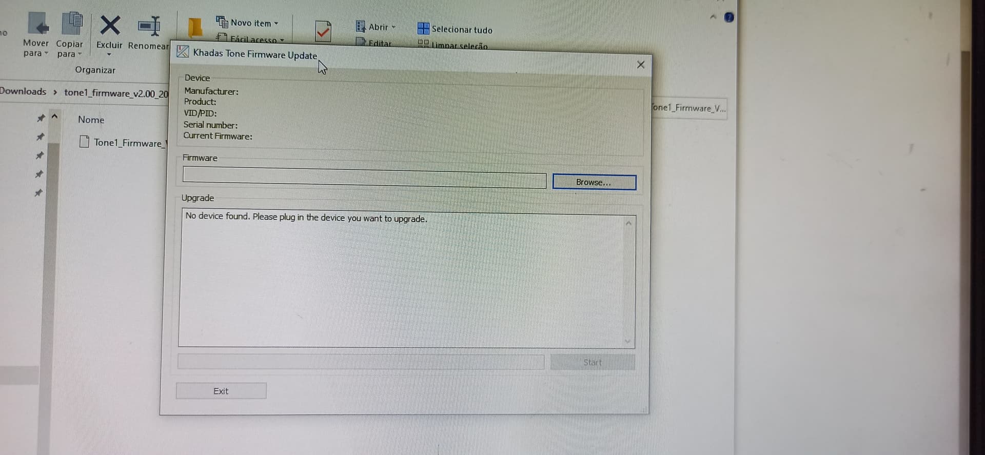
I’ve followed the solution 2. The board is On but no device on Windows. My Tone board is the generic version, and normal USB (from USB C connector) is working).

Any tip?
Thank you.
Hi,
I’m using this tutorial to separate data and Power
I’ve followed the solution 2. The board is On but no device on Windows. My Tone board is the generic version, and normal USB (from USB C connector) is working).
Any tip?
Thank you.
Hi Mr_Kholl,
Please check:
if that not work, @Eric68 will help you, thanks.
Hi Kenny,
Thank you for the quick reply.
No, it’s not. Only GND of the power line.
I didn’t see the GND of data plugged in the tutorial, maybe I’m missing something.
I’m using only 4 wires like the example. Pins 2 and 5 aren’t in use.
Hi Mr_Kholl,
Apologize for the above description caused you to misunderstand. We will correct the description on the blog later, thank you for your feedback. ![]()
GND needs to be connected to the data port and power port so that the USB data port can have a correct reference level. You can try connecting the GND of the data port and the power port together to see if that solves the problem.
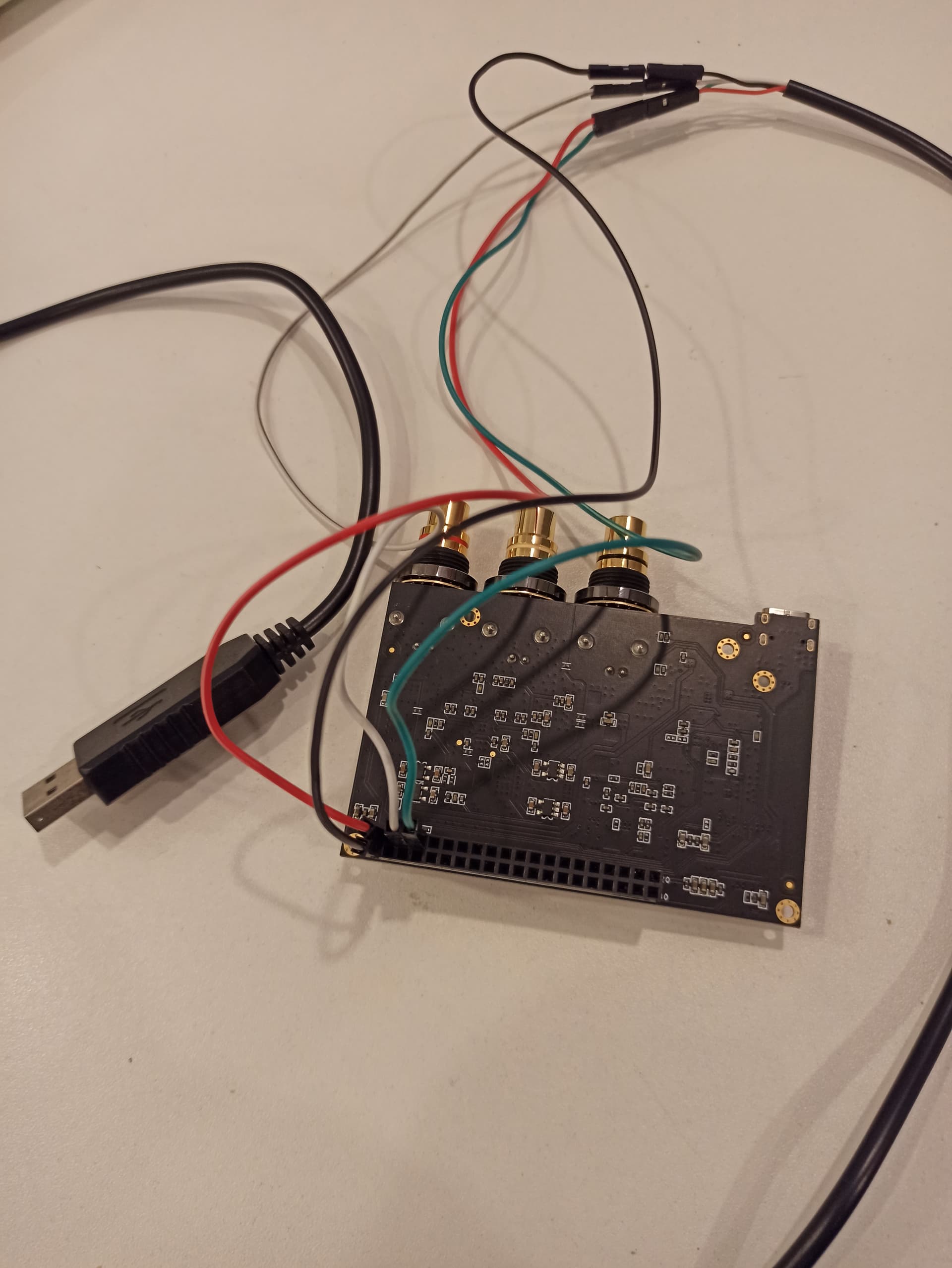
Could you help to take a pitcture here to show the connection of the entire data cable and power cable?
thanks
Hi Kenny,
No problem at all!
Lets check:
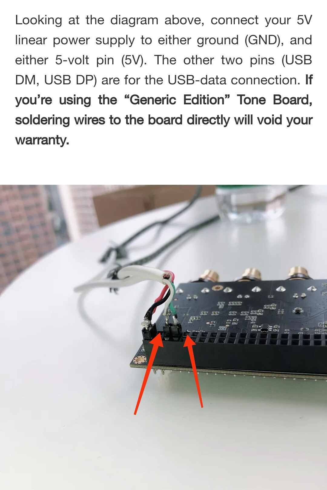
Tone PIN 1 → 5V of linear PSU
Tone PIN 21 → GND of linear PSU
Tone Pin 3 → DM of USB cable
Tone PIN 4 → DP of USB cable
USB GND → GND of linear PSU
Or
Tone PIN 5 → GND of linear PSU
?
you can try:
Thank you Kenny,
Gonna try this, update you soon!
Hi Kenny,
Didn’t work. I made the exactly connections you said, windows don’t show the device.
Any other tip?
Anyway, I will try the Method 1 (USB C Splitter cable).
@Eric68
Please check this, thanks
Hi
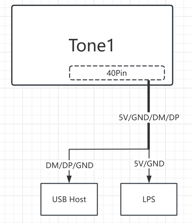
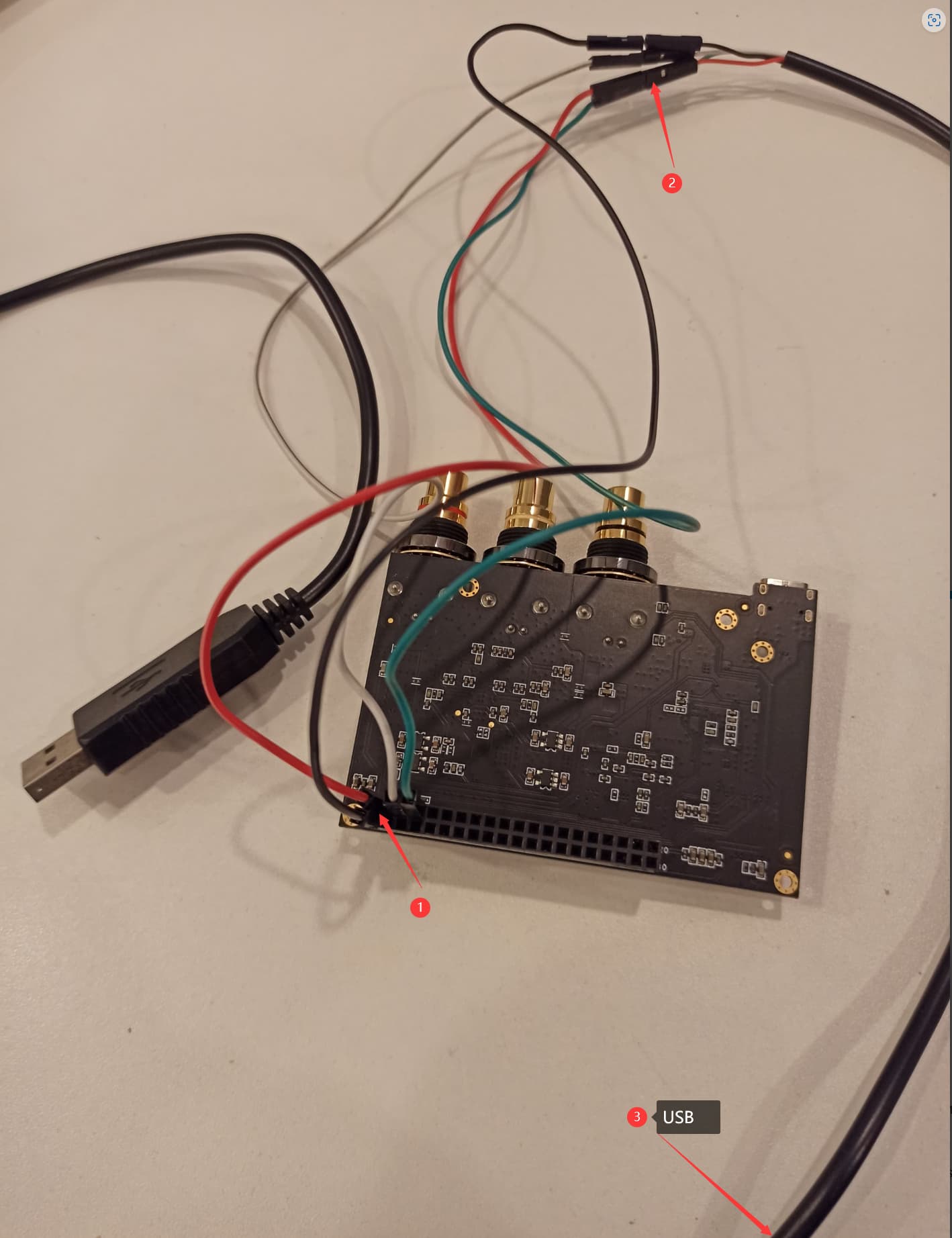
I suggest you can follow my block diagram below.
Make sure that 40pin USB signal should not be reverse.
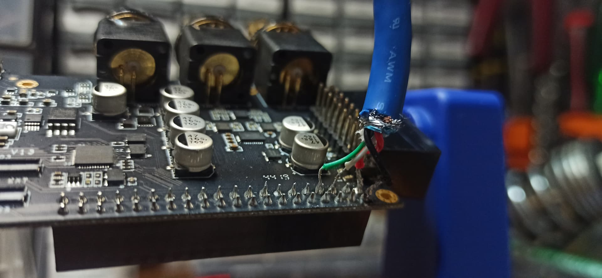
White——>DM(PIN3)
Green——>DP(PIN4)
Make sure that DM and DP should not be connected together.
The connector of this cable which power and signal are separated should be better to use USB A plug to connect to USB host, USB C is not recommended.
The connector of this cable which power and signal are separated should be better to use USB A plug to connect to LPS, USB C is not recommended.
The copper wires of GND should be divided two kinds of wires, one is to USB host, another one is to LPS.
Hi Eric,
The connections you mentioned is exactly I’m doing here.
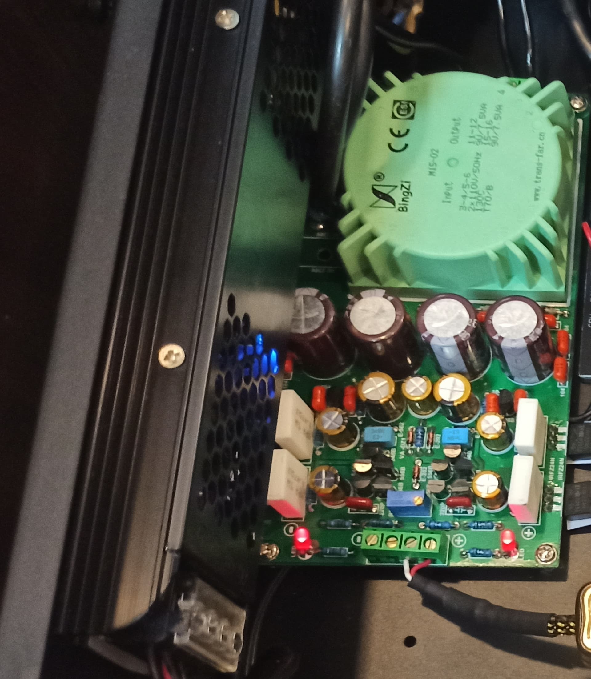
The only difference is that my 5V linear PSU is internal and has bornes + and - instead USB.
Anything else to check?
Hi
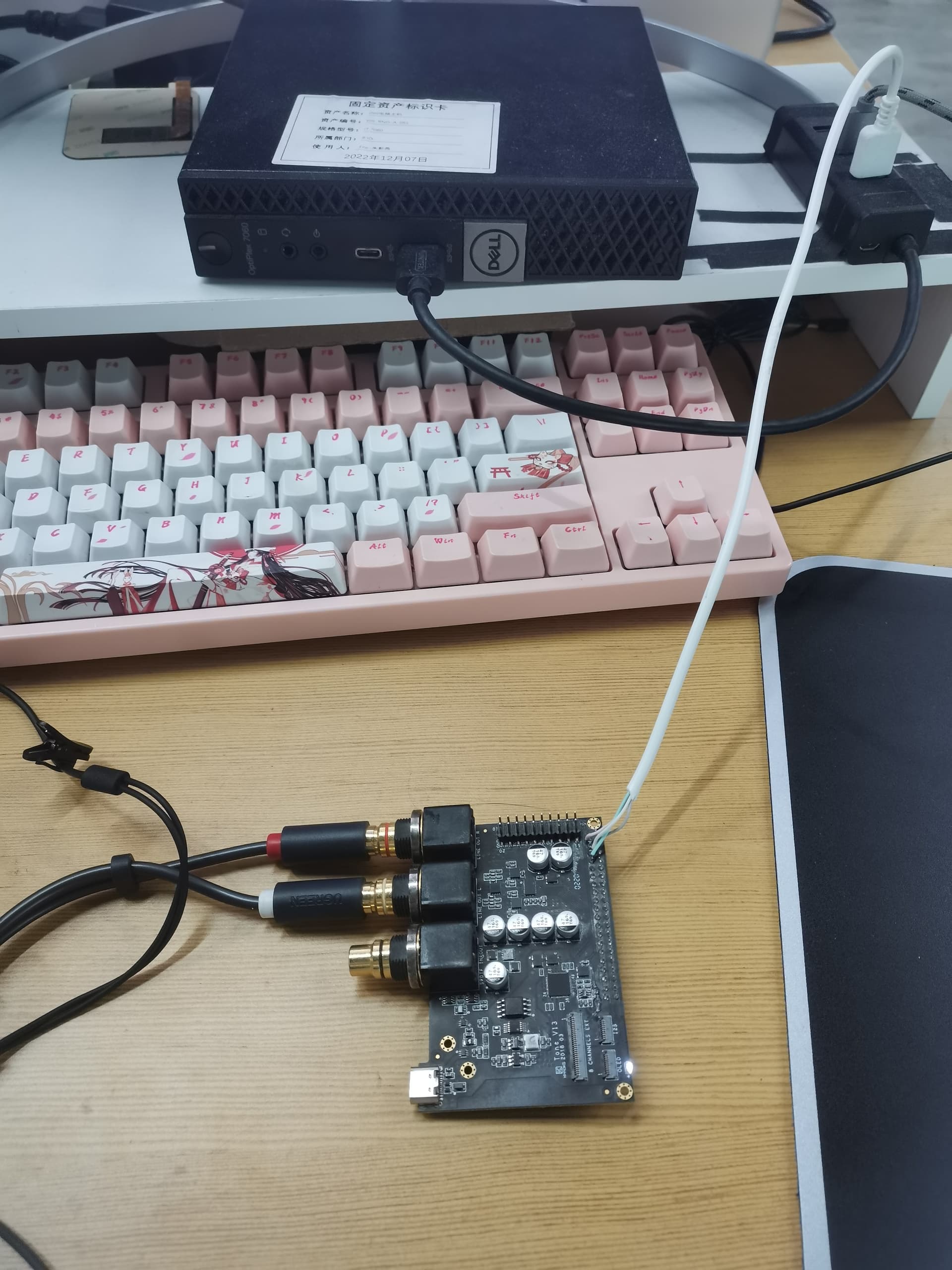
Can you take a clear photo about the connection between Tone1 and USB Host?
I see the picture you show, the color of the GND is white, normally, it should be black. You can check it. And can you take a clear photo about the DIY cable which the power and USB signals are separated?
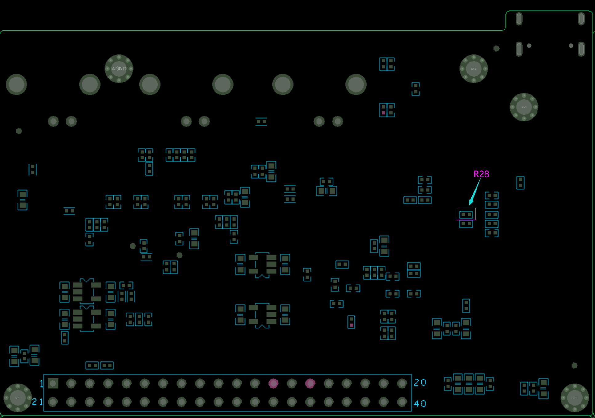
Do you have a multimeter to test the voltage of R28(any sides)? The postion of R28 is shown below.
Hi Eric,
Thanks!
1 - Ok I will provide you.
2 - Don’t worry about the color, it’s a custom 2pin cable, in this case gnd was white not related to DM wire of USB.
3 - Ok will test it.
Update you soon.
PS: I’m considering using Tone 2 Maker in the project too, is it the same pinout on gpio?
Hi
The pinout of tone2 maker’s 40PIN header is the same with tone1 about the USB signals and power.There are also some differences about them.You can find the schematic of tone2 from here.
The definition of 40PIN header is at page 9.
Hi Eric,
Well, I got a VIM version and I had the same result, the board turns on but no device, with USB cable directly (xmos driver) is working perfectly.
The value of R28 I measured is 0,84v.
Just for test I set a simple USB cable pin to pin and plugged it on PC, same result: Turns on but no device.
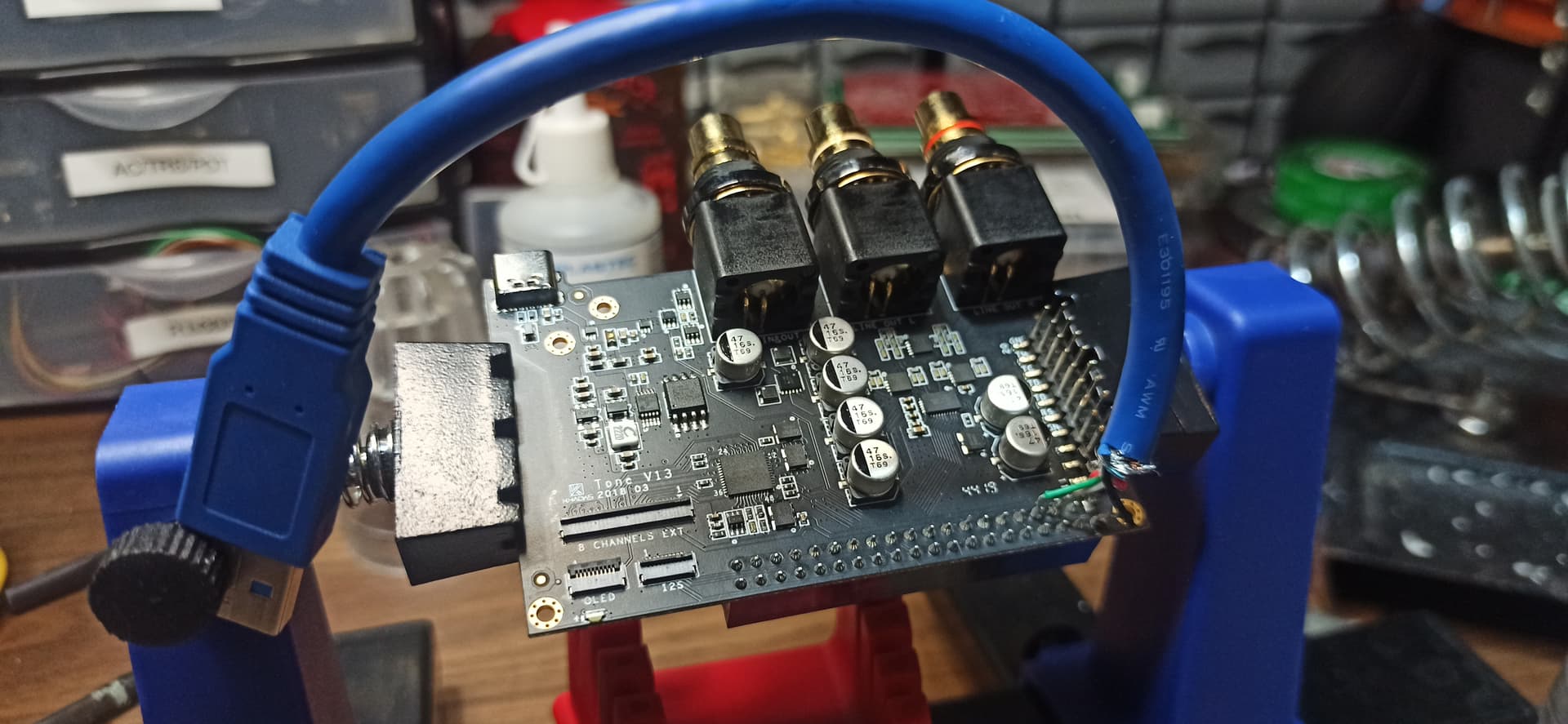
The photo is of my new board (VIM version).
Hi
Sorry, I just had a 5 days holiday to go back my hometown.I will have a try as your connections.
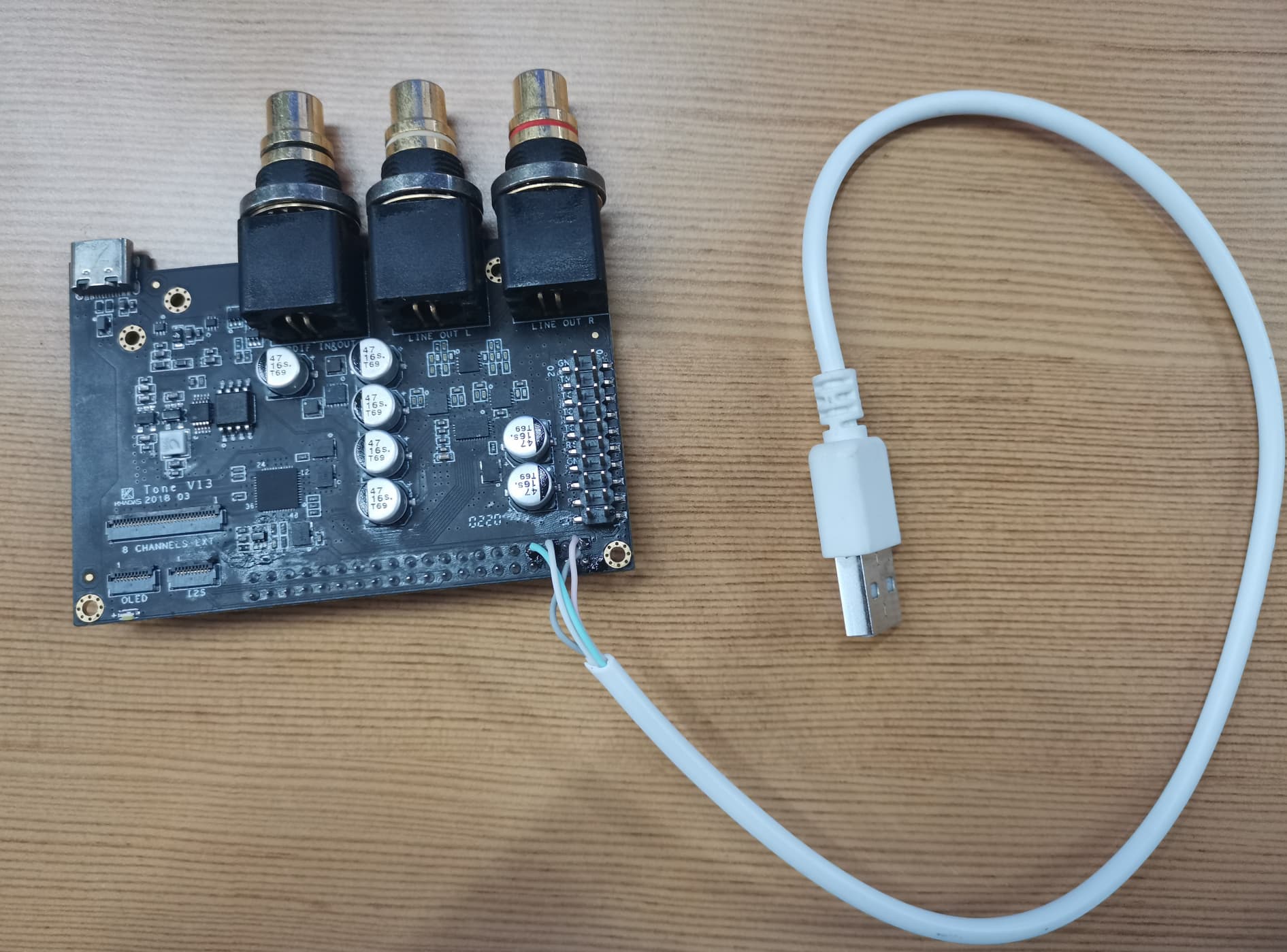
Hi
I have a try as you same connections, it’s OK, I also take a photo with it.
And I see your connections,there are also something improper.
Hi Eric,
Thanks for the valuable info!
In fact that cable with Dupont connectors was just for testing, but you was right:
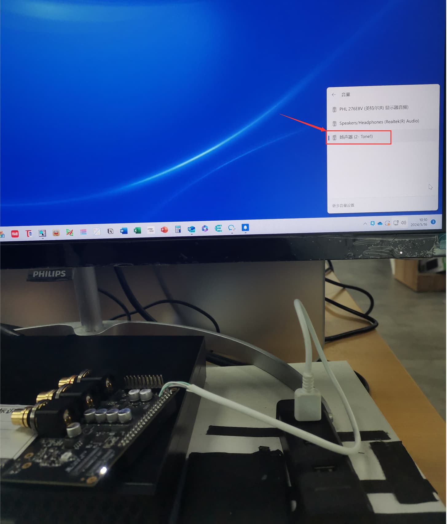
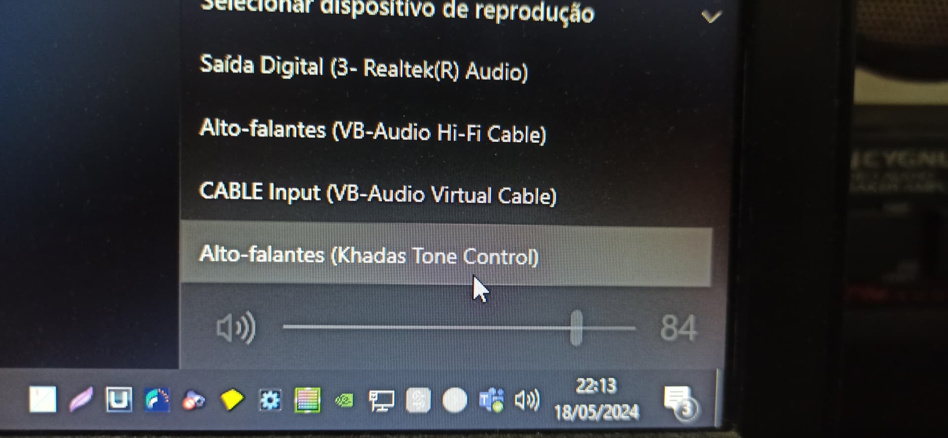
I got a short, good quality and shielded cable and now I can see the device on windows:
The only difference is that the Vim version is appearing as Khadas Tone Controller and the Generic version is Tone 1, but it’s happening with regular USB cable too (why?)
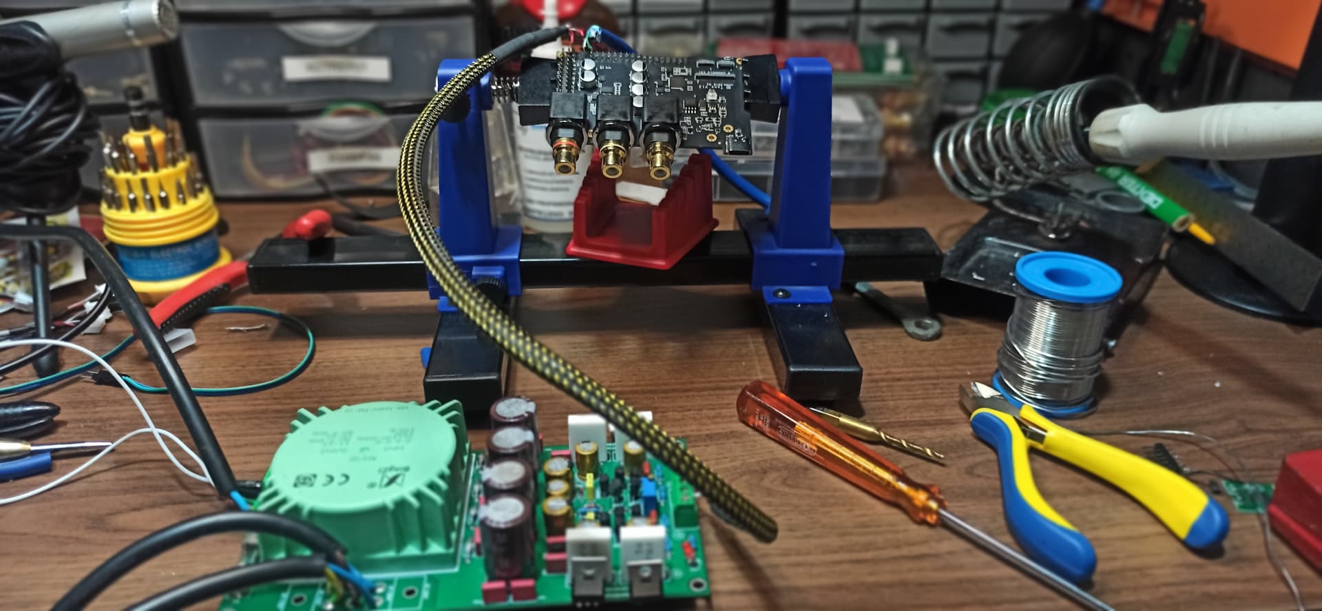
Anyway the next step was test with my linear PSU, so I took out the red wire (5v) and replaced it with the PSU 5v, and placed the GND of the PSU together with the GND of the USB.
Windows can recognize the board but the sound now is very distorted and strange, any tip?
Hi
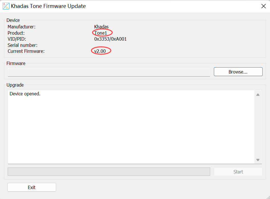
Can you screen shot about khadas DFU when you connect tone1 to PC?Such as the following picture, to confirm the firmware.
About the distorted,you try to supply power by USB A not PSU.
Hi Eric,
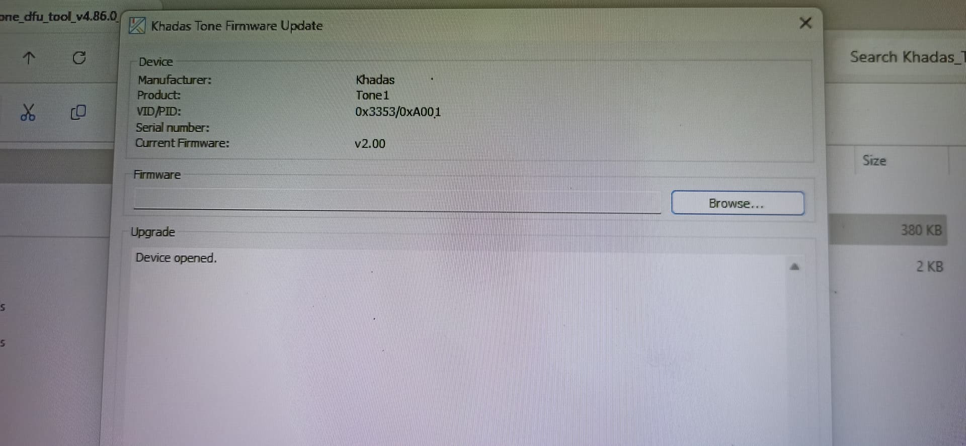
I ran DFU in both boards:
The Generic version:
The VIM version:
Regarding the distorted audio:
When I plug the cable with complete USB A (5v+GND+DM+DP) the sound is ok, when I plug the modified USB A (DM+DP+GND) and 5v+GND in my linear PSU I got the distorted sound.
Why I’m insisting on linear PSU? Because the switching psu on my PCs are generating some annoying EMI noises (example: when I move a wired mouse) so I’m trying to avoid switching PSUs on DACs.