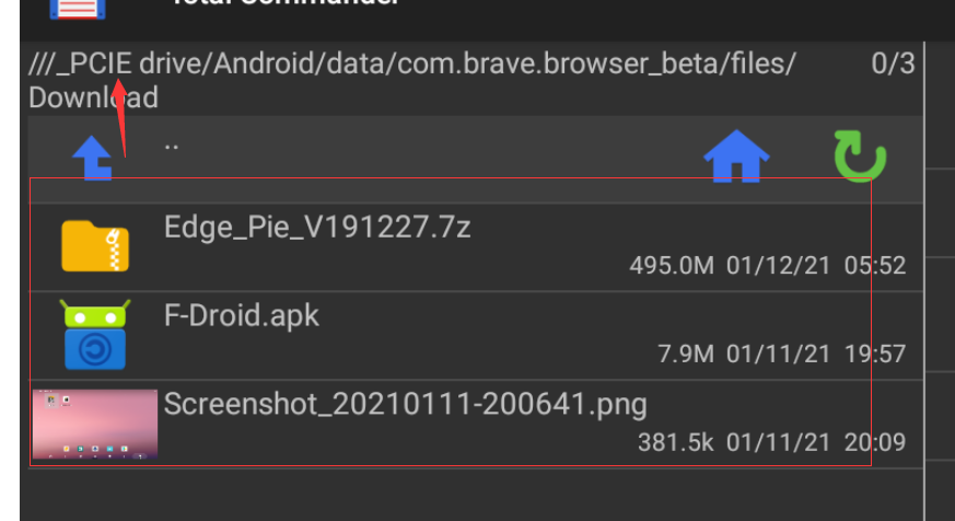
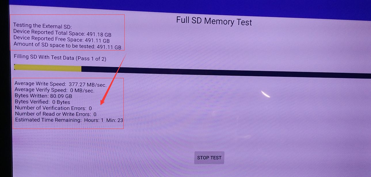
I had no issue writing to the SSD on Android 9 Firmware version 20190912. Not sure what is causing your issue. Hopefully goenjoy can determine something from the log.
Regarding the method you are using to physically mount the SSD to the Edge-V. Without a way to secure the drive, I wonder if a possible misalignment between the SSD and the M.2 slot could be contributing to the issue.
The VIM’s guide shows the connections, for clarity I changed VIM’s to Edge-V…
Tool Tool Pin GND: <—> Pin17 of Edge-V’s GPIO
Tool Tool Pin TXD: <—> Pin18 of Edge-V’s GPIO (Linux_Rx)
Tool Tool Pin RXD: <—> Pin19 of Edge-V’s GPIO (Linux_Tx)
Pay close attention to the TX and RX lines. The tool’s RX line connects to the GPIO’s TX pin. The tool’s TX line connects to the GPIO’s RX pin.
Colors shown in this example may not be the same colors as yours…
A look at the Edge-V’s GPIO, notice the numbers printed on the PCB at either end of the GPIO connector. 1&21 at one end, 20&40 at the other end. You will be concerned with the end and row with 20. Specifically pins 19, 18 and 17, as shown here…
Once the serial tool is connected to the Edge-V, install Putty on your PC. Connect your Serial tool to the PC’s USB port. Once installed and running, some settings/info in Putty will be needed to be changed.
Once all is set, click on the Session and click save.
Are you using Windows, Linux or Apple? We need to know what COM port the USB serial tool is on.
Windows example using the Windows Device Manager to ID the COM port…
If you are successful to this stage let me know and we will move to getting the log.
Otherwise, Once all is ready to go, click Open at the bottom of Putty. Boot the Edge-V. Once fully booted you can close Putty. The log will be in Putty’s program folder. goenjoy may want more than the boot log, but by now you are an old pro and will be able to produce additional logs.
Thanks a lot for the instructions. Is there a risk of damaging my computer if the pin assignments in my tool are different? I am very happy with my Edge V max and would not want to lose it. It is no longer available in Poland …
If TX and RX lines get reversed it won’t work but should not cause damage at either end. I have done it before, more than once, never any damage. The GND pin(17) on the GPIO should be connected to the tools GND(Ground) wire. Did your tool come with a legend telling what each wire is for?
If not, assume Black is Ground, White and Green wires are RX and TX. The Red wire is likely “+” voltage/VCC, it will not be used, do not connect it.