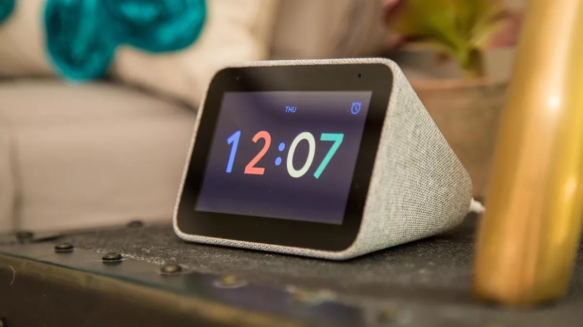
TS050 and VIM3 (Or Edge-V, VIM2, whatever) could be installed. Power would be connected all the time. The screen must be visible in front of a device, and touchable also. I will use this as a kind of installed dashboard for my home IoT.
Direction, size, material, or anything else don’t matter if it could be 3D-printable.
Can anyone help me? If you want I can pay some gratuity.
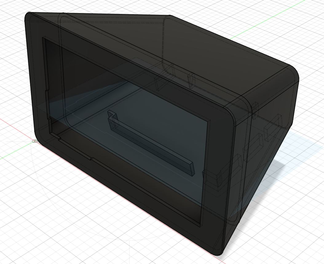
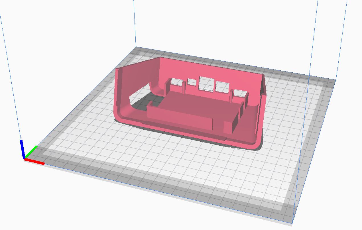
The problem with a shape like this is that design will be driven by the printing tech. With an FDM printer, there is almost no way I can see at the current time a way to print this without a lot of supports for the internal structure. I might see a way to split the rear part of the case in two, a top and bottom shell, that could make that easier. But this is a 20 minute sketch:
@ethanfe that looks cool.
the only things you need to complete it is give it a groove for the TS050 to sit in, and some mounting holes for the VIM3, if you need drawings of the devices, or 3D models, you can check here for VIM3, and Touchscreen.
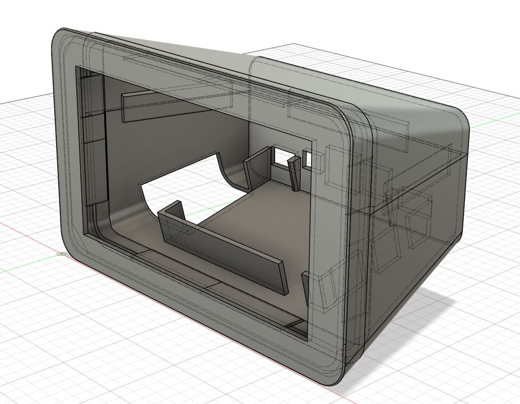
My intention here is that this shell is broken into 3 parts for best FDM printing. Even with these breaks there will need to be some supports. You will need to work out what works best for your printer. The design is intended that the three parts are super glued together on the face of each tab. The VIM3(L) board will need to be hot glued with some small dots to the internal supports. Once an M2X board and a heatsink is on the VIM, you lose the holes for mounting anyway. It wouldn’t need to be extensive. I also expect that the cut outs in the rear for the ports might need to be sanded / coaxed to fit perfectly. I made them slightly oversized and you might get lucky.
I did not put in a recess for the touchscreen, as in my experience, the recess would be so shallow the print supports in this area are annoying to clean up.
The intention of the design is to print with the face down on the printer, the top side down and the bottom side down. Again, you might have to play with this.
I did not put any ventilation holes on the bottom, but I lifted the board a good height above the bottom surface to allow more airflow. This with the cut out for the buttons should allow enough air flow, but again - tune as you see fit.
Final note - the touchscreen opening will need to be shaved or sanded for a perfect fit. I found enough variation in fit from printing tolerances to screen manufacturing tolerances. I sized this opening to the largest tolerance that Khadas put in their docs, but form experience you will need to fit to your specific screen.
Nothing to add at this moment.
I’m considering a tiny thumb usb mic to implement voice control, but optionally.(In my experience, voice control with GA for device is not reliable until now)
I’ll use BT speakers so no need of space for internal speakers.
Maybe some GPIO sensors might be considered in the future, but ATM, enough with TS and SBC. Thanks.
Yeah the top has plenty of room left for whatever speakers you want to add. Without actually having something specified and knowing their requirements and dimensions I can’t really do much to add them.
I would have suggested a few breathing holes at the top, but I guess the whole contraption is big enough to have enough space without suffocating the fan,
But he provided only the STL files, which are used to generate gcode from a slicer in order to 3D print something. However, in order to generate those STL you need the actual design file - the “source code” if you will (dwg, f3d, dxf, so on and so forth.) If the f3d (or comparable) file is referenced in a link in that post, I don’t see it.
I misunderstood “design” with 3D source files,
perhaps ask @ethanfe if he could provide it for you,
stl files were shared to give one less step when ordering 3D prints for Sean_Yi.
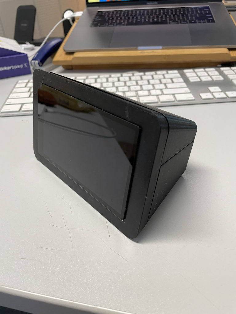
It is not bad really. (I haven’t finished the surface with sandpapers, and not glued the parts yet.)
The screen and SBC fit perfectly in their position without any bolts or glues. It’s nice.
But there would be some suggestions for improvements.
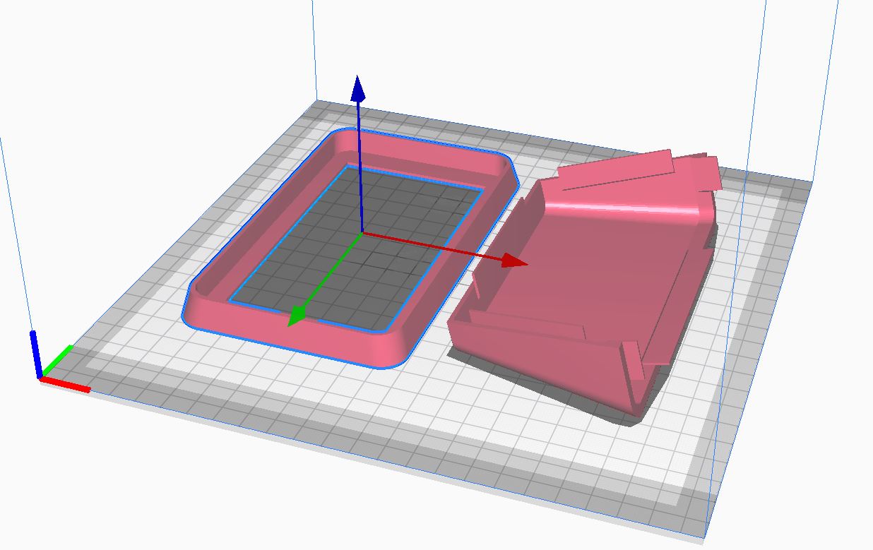
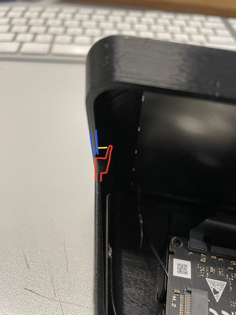
Screen part is not fit with the top/bottom guides. (Hard to describe this. Sorry I don’t have a native tongue of English)
The blue is the Screen part, The red is the bottom part. The yellow is the gap between edges of these two parts. Thus the screen part couldn’t be fixed without glue.
The fan would face to the bottom. I think some ventilation holes would be nicer in the bottom parts. (I will attach some rubber pods beneath the bottom parts to prevent sliding. It will lift the device from the ground so the vent hole will work.)
GPIO pins are blocked. Hmmm. at this moment, this is not my problem. But when some other man want to use GPIO, it might be the issue.