Which Khadas SBC do you use?
VIM3
Which system do you use? Android, Ubuntu, OOWOW or others?
Android
Which version of system do you use? Khadas official images, self built images, or others?
Android official source code (android-13.0.0_r7 tag TP1A.221005.002 + Linux kernel (branch android-amlogic-bmeson-5.4))
Please describe your issue below:
Hi everybody.
I’m using Android 13.0.0_r7 built from official android distributions with the kernel 5.4 provided by google as described in the official Android documentation (since VIM3 is an officially supported android board): https://source.android.com/docs/setup/create/devices#vim3_and_vim3l_boards
The aim of the project is to connect an IMU sensor asm330lhhx (the driver is on github but unfortunately I can’t use more than two links per post because I’m a new user anyway the project is st-mems-android-linux-drivers-iio, branch master relative path drivers/iio/stm/imu/st_asm330lhhx) through an SPI interface configured in MODE 3 (CPOL=1, CPHA=1). The available SPI interface pins on the VIM3 board sp1cc seems to be connected to the expansion pins of the 2 x 20 connector as explained in this thread VIM3 GPIO "WiringPI" SPI - #24 by ChiaHungMou
VIM3 SPI:
PIN37: GPIOH_4/SPIB_MOSI → type ALT2
PIN35: PWM_F/SPIB_MISO → type ALT2
PIN15: UARTC_RX/SPIB_SS → type OUT
PIN16: UARTC_TX/SPIB_SCLK → type ALT2
After configuring the device tree to be able to use such SPI interface with the “software” Chip Select (CS) on GPIOH_6 (active low) with the following DT fragment:
(file meson-khadas-vim3.dtsi)
+&spicc1 {
+    status = "okay";
+    pinctrl-names = "default";
+    pinctrl-0 = <&spicc1_pins>;
+    cs-gpios = <&gpio GPIOH_6 0>;
+
+    asm330lhhx@0 {
+        compatible = "st,asm330lhhx";
+        spi-max-frequency = <1000000>;
+        spi-cpol;
+        spi-cpha;
+        reg = <0>;
+        interrupt-parent = <&gpio_intc>;
+        interrupts = <GPIOA_0 IRQ_TYPE_LEVEL_HIGH>;
+        st,int-pin = <1>;
+        wakeup-source;
+    };
+};
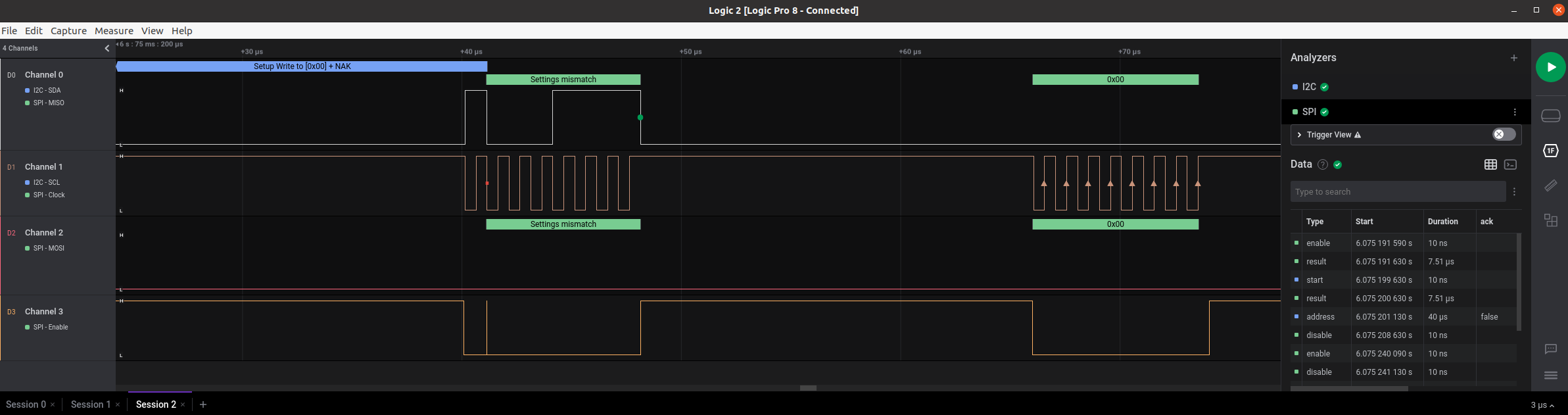
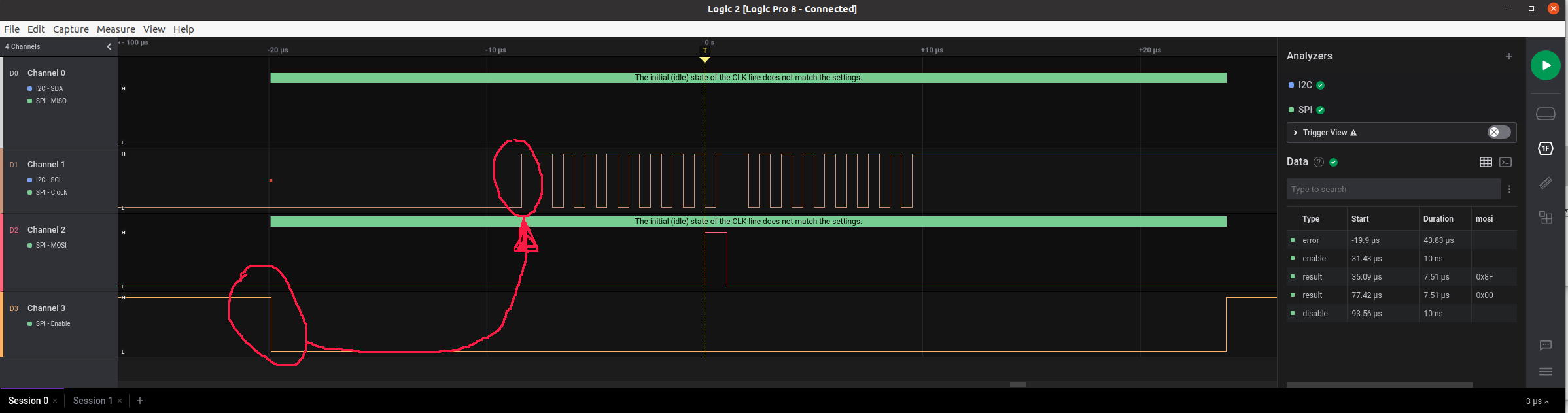
the SPI interface seems to work and MISO/MOSI/CLK/CS signals are visible on the lines.
What is observed from this line is that the CS pin is asserted (goes low) when the CLK pin still not activated, while in SPI mode 3 I expect that the CLK is already set when the CS is asserted (see red line in picture), this behavior does not allow to read correctly from the SPI slave sensor device.
Another strange behavior is when I enable the HW management of the CS (instead of passing CS gpio line through device tree) by changing the default DT (file meson-g12-common.dtsi:):
spicc1_pins: spicc1 {
        mux {
                groups = "spi1_mosi",
                "spi1_miso",
+               "spi1_ss0",
                "spi1_clk";
                function = "spi1";
                drive-strength-microamp = <4000>;
        };
};
(file meson-khadas-vim3.dtsi):
+&spicc1 {
+  status = "okay";
+  pinctrl-names = "default";
+  pinctrl-0 = <&spicc1_pins>;
+
+  asm330lhhx@0 {
+      compatible = "st,asm330lhhx";
+      spi-max-frequency = <1000000>;
+      spi-cpol;
+      spi-cpha;
+      reg = <0>;
+      interrupt-parent = <&gpio_intc>;
+      interrupts = <GPIOA_0 IRQ_TYPE_LEVEL_HIGH>;
+      st,int-pin = <1>;
+      wakeup-source;
+  };
+};
in this case what is observed is that the CS pin of the SPI is asserted at every single byte transfer while as we know a SPI read and write internal registers involve at least two byte transfer, for example a read operation of the WHOAMI register of the ASM330LHHX made by this code:
err = regmap_read(hw->regmap, ST_ASM330LHHX_REG_WHOAMI_ADDR, &data);
is translated by the kernel regmap API into a SPI write operation of the ST_ASM330LHHX_REG_WHOAMI_ADDR (0x0F) and a SPI read operation to read the value of this register, this must be done within the same CS and not by asserting it twice.
Could you help me to solve this issue? Do you know if this can be solved simply by configuring the SPI in another way or is it necessary to change the SPI driver?
Thanks and Best Regards,
Marte.