Hello. I would like to install the Tone Board DAC into an old CD player. I have identified a good power source, my question is the connection to the board for SPDIF input. It looks like pin 13 and pin 33 on the 40 pin location. I would just like some confirmation if anybody has done this connection before. Tips, or caution. Thanks.
No6: 40-Pin Header Pinout (J1)
| Signal | Pin | Pin | Signal |
|---|---|---|---|
| 5V_1 | 1 | 21 | GND5 |
| 5V_2 | 2 | 22 | OLED_SCL |
| VIM_DN | 3 | 23 | OLED_SDA |
| VIM_DP | 4 | 24 | GND6 |
| GND | 5 | 25 | - |
| - | 6 | 26 | - |
| - | 7 | 27 | VCC_3V3 |
| - | 8 | 28 | GND7 |
| GND | 9 | 29 | I2S_SCLK |
| ADC0 | 10 | 30 | I2S_MCLK |
| - | 11 | 31 | I2S_SDO |
| - | 12 | 32 | I2S_LRCK |
| VIM_SPDIF | 13 | 33 | I2S_SDI |
| GND3 | 14 | 34 | GND8 |
| UART_RX_AO_B/SPDIF_MODE gpio506 | 15 | 35 | OLED_PWREN |
| UART_TX_AO_B/SPDIF_IN_MODE gpio505 | 16 | 36 | - |
| GND4 | 17 | 37 | OLED_RST |
| Linux_RX | 18 | 38 | - |
| Linux_TX | 19 | 39 | MUTE |
| VCC_3V3 | 20 | 40 | GND9 |
i will try to check it soon
Thanks for the speedy reply. I guess I’m confused if I need one ore two connections. The coaxial out from the cd player has two wires. SPDIF in on pin 13 would be the “center” wire and the “outer” wire would be on pin 33. I’m not 100% sure of this, that"s why I’m asking. Thanks again.
On the VIM’s GPIO, pins 13(Signal)and 14(Ground) give SPDIF output, therefore, I assume the Tone Board’s GPIO SPDIF input is also via pins 13 and 14.
Pins 15 and 16 appear to have SPDIF function, but I think these are used to determine the TB’s SPDIF configuration(in or out) but I am not sure on this.
Signal wise, 13 for center conductor(Signal) and 14 for outer conductor(Gnd/shield).
Thanks for the clarification. That makes perfect sense to me. I will let you know how it turns out.
I think any of the ground pins on the GPIO would also work, but using 14 keeps it all together, tidy. 
Keep us posted.
Now the hard part. What is the best way to connect wires to the board?. I’m a little concerned about soldering in that tiny area. Does the 40 pin header push in tight?.
I have the VIMs version, its GPIO header came mounted, so I do not know what sort of fit the header has in the TB. It may fit snugly, but I don’t think that would result in a reliable electrical connection.
I am pretty adventurous when it comes to soldering, I have years of experience with it, the adventure is due to my aging eyesight. 
I understand your apprehension about it. Maybe a shop near you could perform the soldering for a small fee.
Until then, it just might be easier to route the SPDIF cable externally, from the jack on the CD player, to internally to the TB’s SPDIF jack. It would all be hidden in the back of the CD player,… nobody looks back there anyway. 
What will be the TB’s source of power?
1 Like
SPDIF have TWO wires its signal + GND
we have 2 variants
-
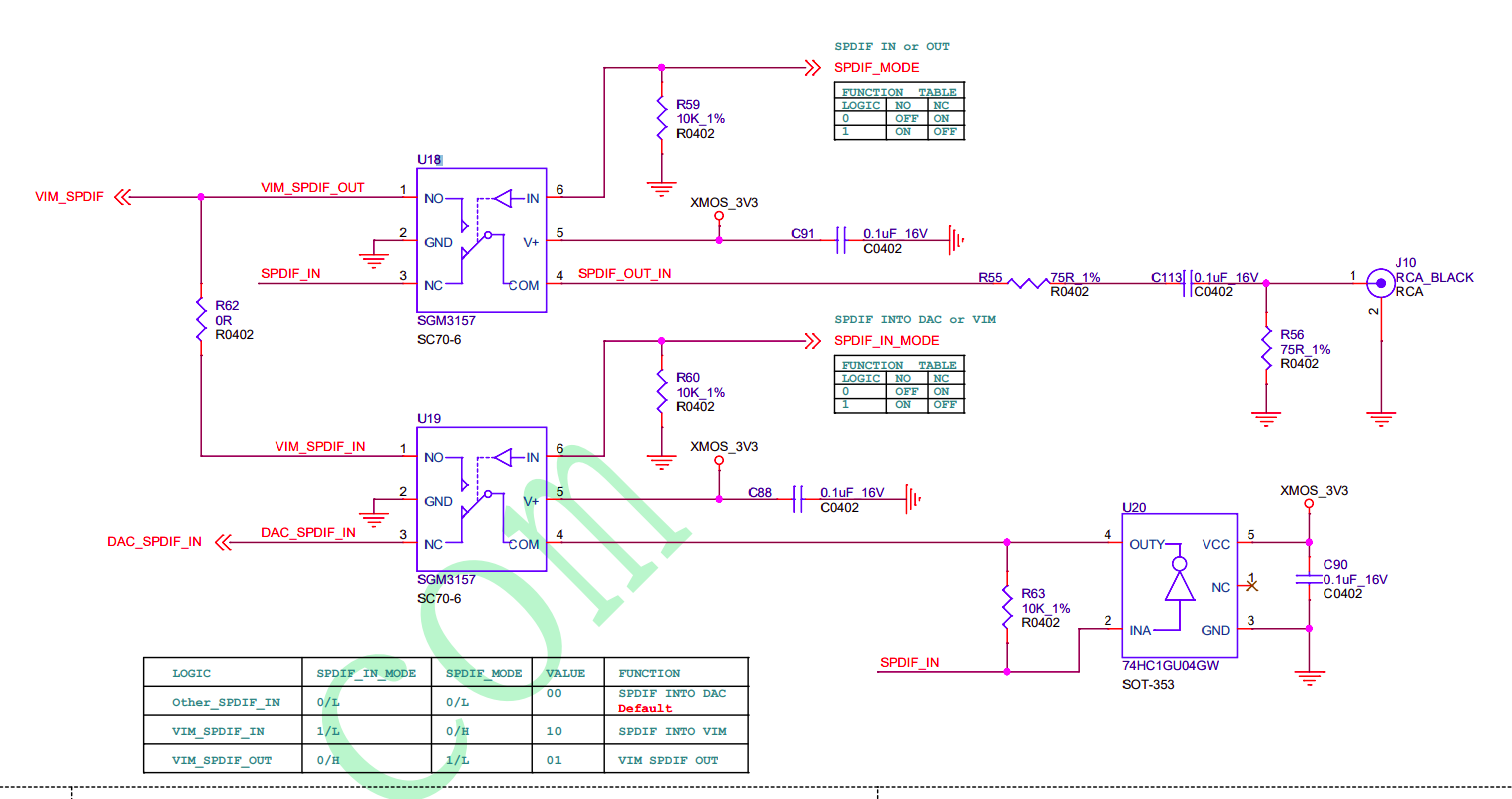
we can send SPDIF signal to RCA connector (black) - this way no need any manipulation - and we can listen ANALOG OUTPUT from L+R RCA connectors (red+white )
-
we can send SPDIF to VIM_SPDIF 13 pin on header - but we need configure SPDIF_MODE and SPDI_IN_MODE pins to setup level 0+1
1 Like
Running a short cable external was my original plan. I have found a good 5 volt source within the cd player from the IR remote circuit that is not used. I know what you mean about adventure due to reduced eyesight. I will look for a smaller solder tip and magnifying glass light today. Thanks again.
1 Like
Does this change need to be done with the laptop and USB? . I believe everything else is looking good. The board is installed and works with a jumper from digital out to spdif in (default mode)
I don’t know how much soldering experience you have, so forgive me if some of what follows sounds elementary.
The TB’s Printed Circuit Board(PCB), like most modern PCBs, is sensitive to too much heat when soldering. Too high temp or too long on the joint can result in pad or trace lifting, and may result in serious damage to the PCB. A temperature controlled soldering iron will help prevent this. Also good, clean solder and paste flux will reduce the time heat needs to be applied to make a good joint. A low temp solder may also be helpful.
I purchased a cheap(less than $60USD) solder station on the Bay, it has a temp controlled soldering iron and also offers temp controlled hot air. If I were soldering the GPIO header to the TB, I would probably try the hot air and soldering paste first, however, if all I had was a basic pencil type iron, I would use that. I would try the hot air first simply because it still entertains me. ![]()
For either type of soldering methods, tools, and their use, there exists a bazillion video examples and tutorials on the Youtube.
A couple of examples… Hot air soldering, GPIO soldering.
Have fun and keep us posted. ![]()
I used a small butane type tool that I have. It has about medium heat and did the job. I was very careful about the location and time at one spot. The board is in and working with the spdif input from the cd player output. I understand that is the default position, and if I would like to change to pin 13 input I will need to switch position of something. I believe a tiny relay on the board. I have no idea how to do that. I took a couple of pictures, but I’m not sure how to upload. I get some script instead of the jpeg. Interesting note. pin 1 and 21 will power the spdif in but not the USB. I used a cable without power and it would not work. That’s OK I just plug in the laptop with the Khadas supplied cable.
1 Like
Glad to hear you were successful.
As far as the logic used to assign SPDIF input, not sure how to make that happen. I think hyphop will have the solution.
When mounted to a VIM SBC, I assume the SBC sets this condition.
Not sure what the best way to do this on the TB itself would be.
looks like only one way send SPDIF signal to RCA connector - without any aditional manipulation
SPDIF_MODE looks like works only for PASS SPDIF SIGNAL INTO or OUT VIM but not going to DAC
Thanks for the information. If I understand you correctly, the default mode is not easily changed. Probably not something that can be done without access to programming code.
Is the objective just to have all wires inside the CD Player?
still didn’t understand what u meen ?
That was the original goal. I have a short coaxial cable outside the player that works well. I did see in the schematic that the two devices are analog and probably could be switched if one was careful. For now everything works great. Excellent sound quality.
1 Like
If later you want to bring the cable inside the player, you could just solder some small gauge coax cable from the corresponding points on the player’s and the TB’s PCBs.
Getting the switches in the right configuration would seem to be a matter of high or low on pin 6 of U18 and U19. But of course, as you say, analog switches so could be jumpered around too.
I usually try to avoid permanently modifying because my mind changes frequently and next week I may have a different preferred use for a thing.
Hope you are having fun. Enjoy the sound.
Like to see some images of your project.