Smiles… ![]() Dead Silent is the KTB audio
Dead Silent is the KTB audio ![]()
1 Like
I mean no hiss when amplifier turned all the way up. That is “dead silent”.
Works fine!
2 Likes
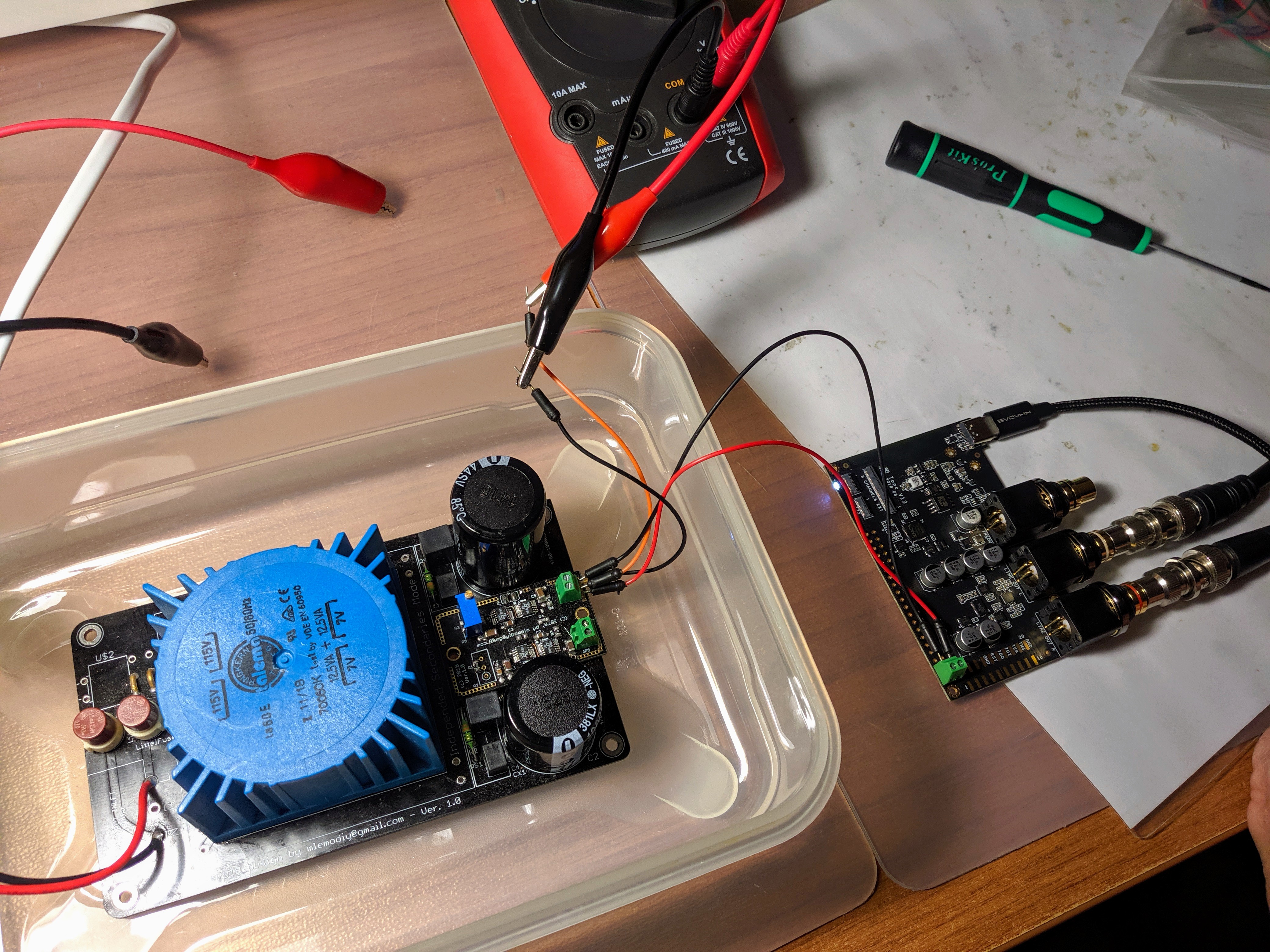
Me and a dyier friend we tried yesterday to power the KTB from two very advanced linear power supplies (especially the first pic) with no success.
The TB reproduced a very distorted sound.
When powering it with a simpler LPS (with LM chip) or with a iFi iPower though iFi iDefender it worked just fine.
The above advanced LPSes use Texas Instruments and Analog Devices (I think) chips to reduce noise further more.
Both were set to 5,1V/1A. When in use KTB needs about 111mA as we measured.
Any ideas why this is happening Khadas team?
2 Likes
Can you provide us the link for the LPS? We need know more details of this LPS.
1 Like
This https://collybia.com/collybia-linear-power-supply/ is the one of the two.
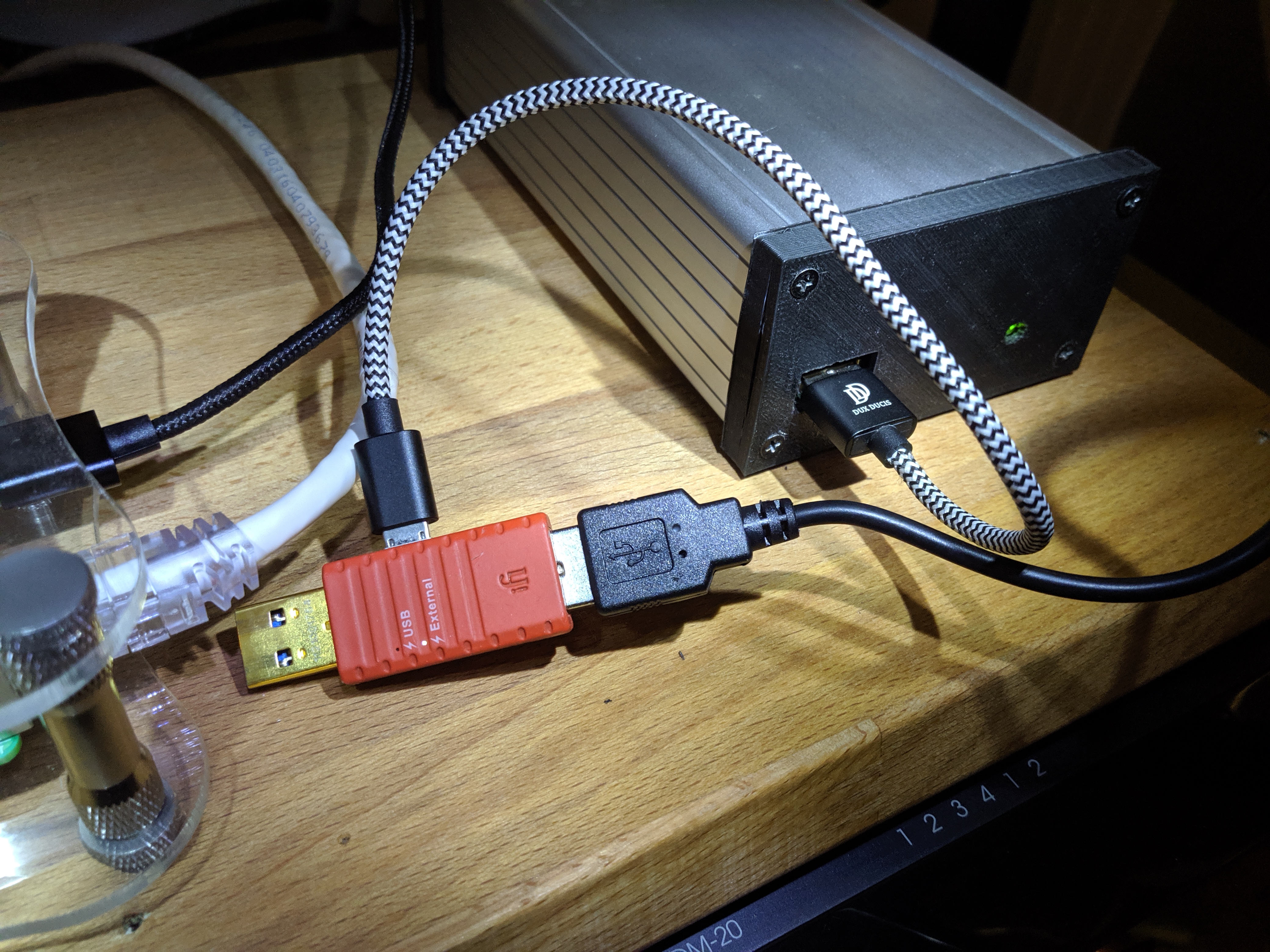
Today back in my place I tried once more with it iFi iDefender for power connection and with the above LPS. Here I don’t have way to connect to GPIO.
After booting everything up and lastly connecting the USB C cable to the DAC it worked OK. I just had to reboot Squeezelite of my piCore player because it didn’t see any output so it didn’t boot properly I suppose.
The procedure was the following:
- Power on the LPS so the iDefender to lock with external power.
- Connect the USB to the rpi
- Boot up rpi
- Connect USB C to KTB
- Reboot Squeezelite because it didn’t see the DAC on boot.
I guess that way I was using iDefender’s power in and not the rpi’s.

About the other LPS which as I said before it is a very sophisticated DIY project I will have to contact the designer first to ask about any info that he would like to share.
Thank you for your interest and quick response!
Michael
1 Like
The Linear PSU https://collybia.com/collybia-linear-power-supply/ gives no technical informations, such as schematic, layout, scope output signal measures…
From what I read, they use Ti TPS7A84A ldo (low drop out) chip.
It’s a very good regulator indeed, BUT, PCB layout is crucial, especially for this part.
I’ve commited some regs with them, hand soldered, I know a little about.
OTO, consider 139€ for a boxed single linear PSU…
You’ll find documented threads about DIY Linear PSU design.
Most geeksboxes requires 5V single PSU.
As TB requires about 120mA (5V), you’ll find better documented kits for this purpose.
Have a look at https://www.diyaudio.com/
Power Supplies section shows a lot of very good single linear PSU…
Cheers
1 Like
Unfortunately I can’t give more info about the Collybia lp supply because I simply do not know.
I am not a diyer so, although I visit diyaudio I can’t build anything.
I have some diyer friends though.
When we make any other tests with KTB I will post here. Along with some info about the second LPS.
I would like to make the second LPS work too because I am very curious if there will be any difference between the two.
Looking forward ![]()
Can anyone explain WHY when I connect the power cable directly on the power supply I get distorted sound but then I put in the chain the ifi iDefender without connecting it to the rpi it works just fine???
The data are transferred through the sbb-c cable connected directly to the rpi.
1 Like
false alarm… it worked ONCE as I described above!
If i recall right it kept working even i unhooked the idefender from the rpi without shutting down or rebooting.
then after reboot … NO!
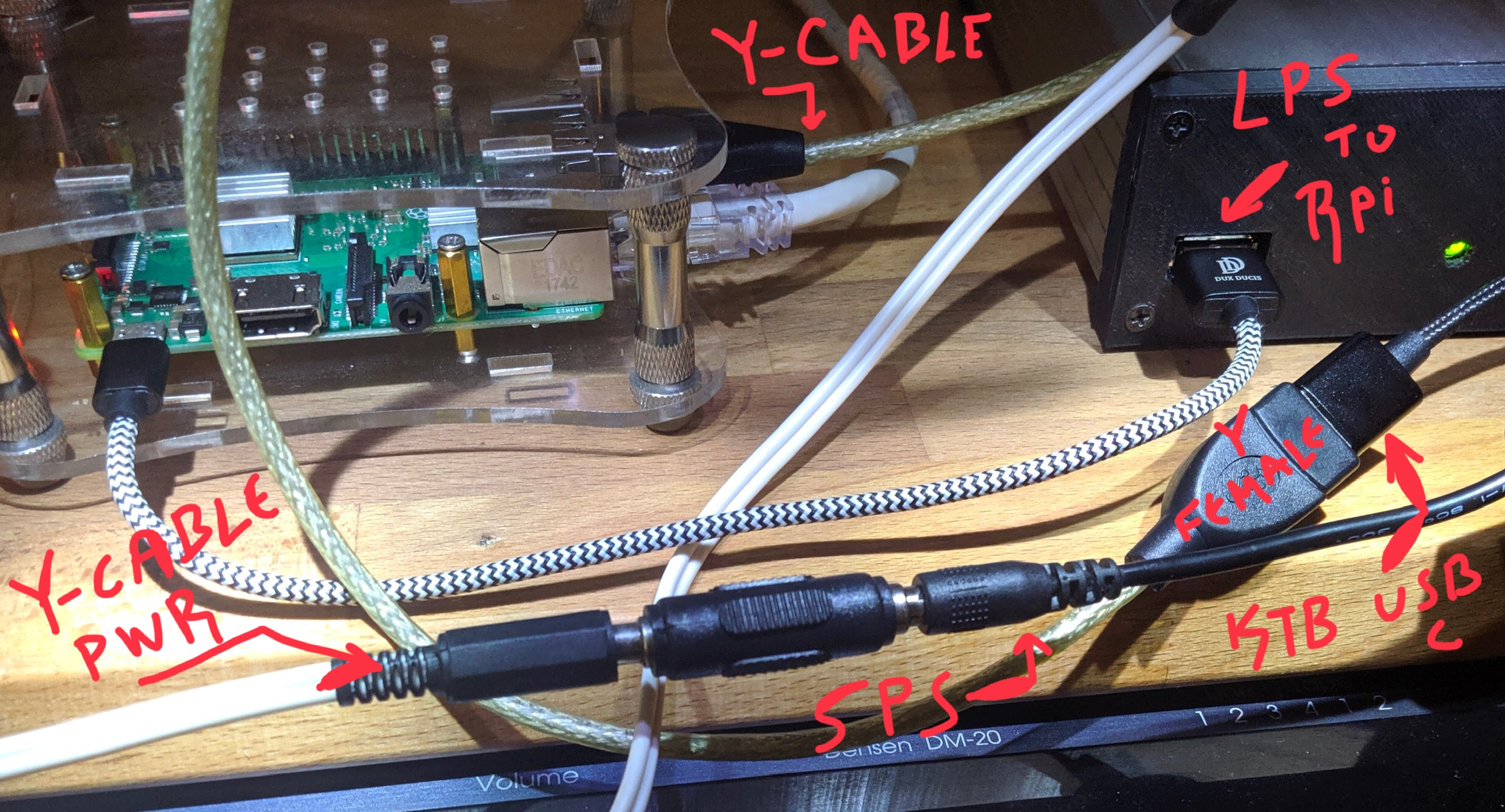
also with the LPS it doesn’t work with Y cable to the usb-c input of the DAC with switching ps it works!
1 Like
One last update for now!
I did the following trick:
I hooked the usb-c cable of the KTB to the rpi through the Y cable but without connecting the power to it. Instead I used all the power supplies I had, linear or not, connected to the GPIO.
The result was that the TB didn’t work with none of them.
So this tells me that one way or another the dac needs some kind of power from the usb to work properly. Regardless the supply to the GPIO.
So with all the respect to the Khadas people and their product may be it isn’t so much “clever” as they stated in a previous post.
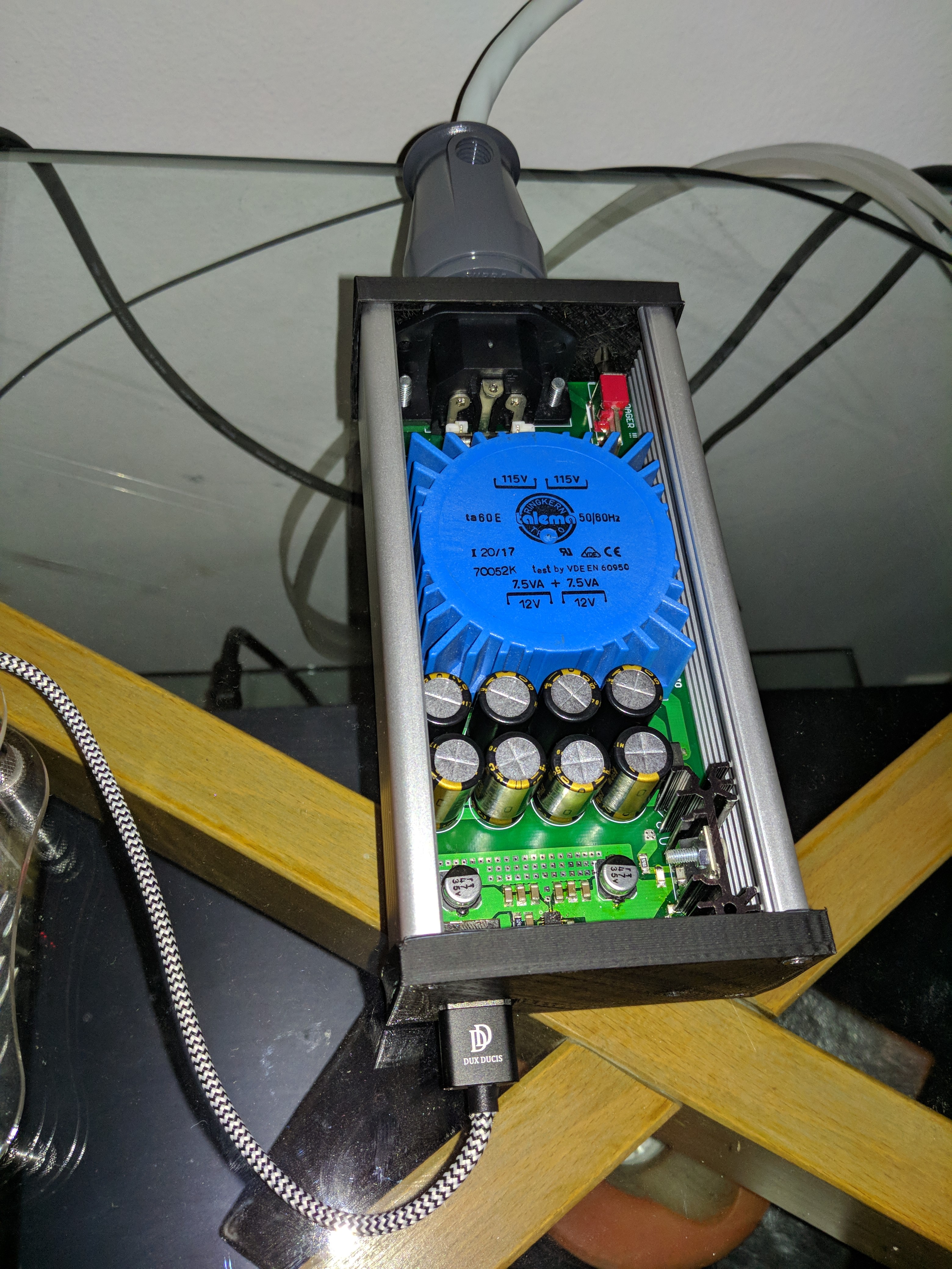
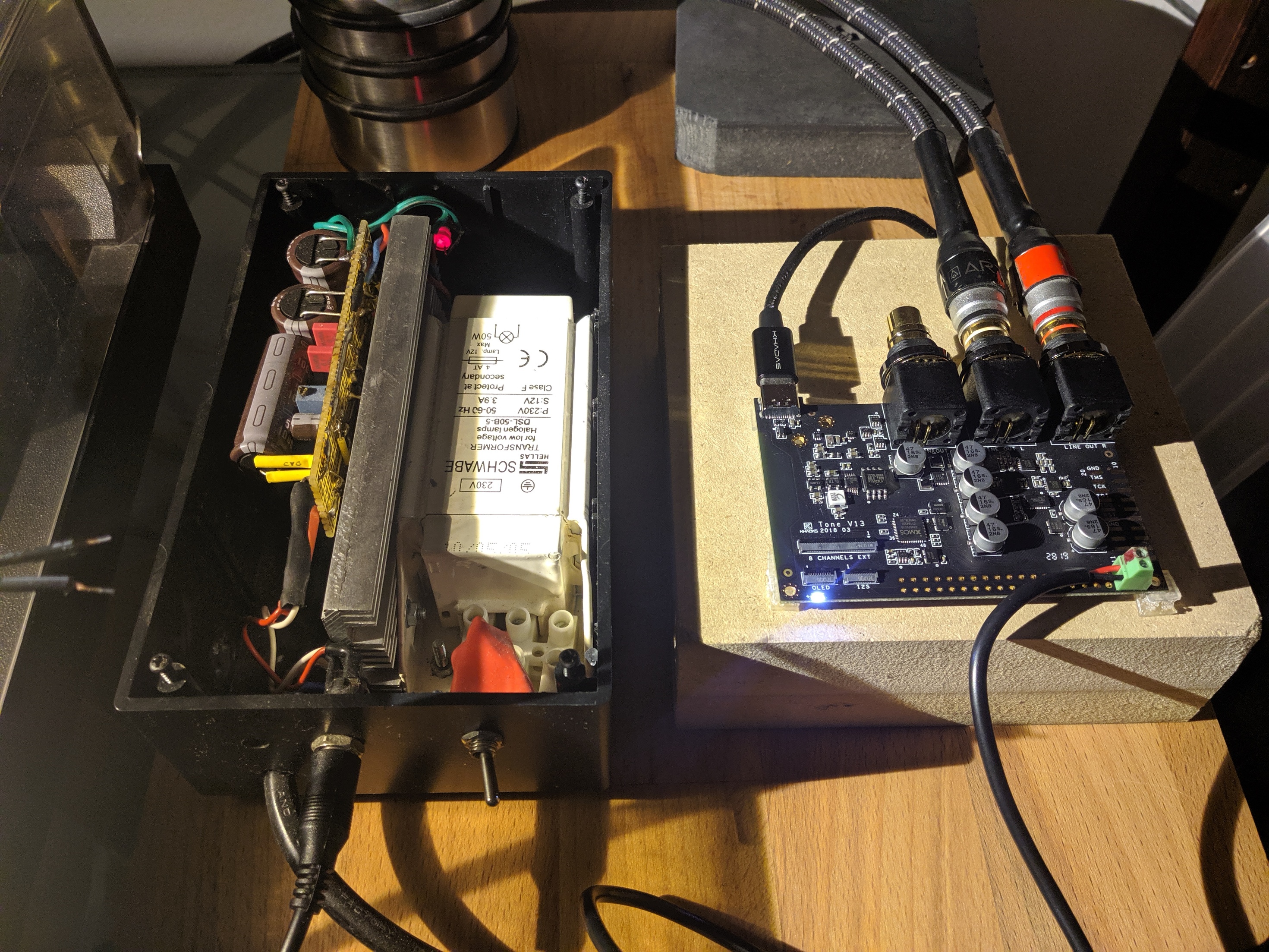
After the above I connected the usb-c cable directly to the KTB and used a simple LPS I remembered I had laying around (shown in the pic) and it worked just fine.
Now why it isn’t working properly in the exact same way but with the more sophisticated LPSes remains a mystery!!
1 Like
@DomieMic65 still very confused after reading 3 of your posts.
Maybe add some hand-drawings showing how the devices are connected, and which configurations worked, and which didn’t?
Thanks 
I don’t think that it matters so much… stick to my last post.
Is it true that the TB needs to see some kind of power from the usb input to work (for usb connection not spidf), regardless of the gpio power?
My last finding is that when only data passed to the usb the dac didn’t work regardless the PS.
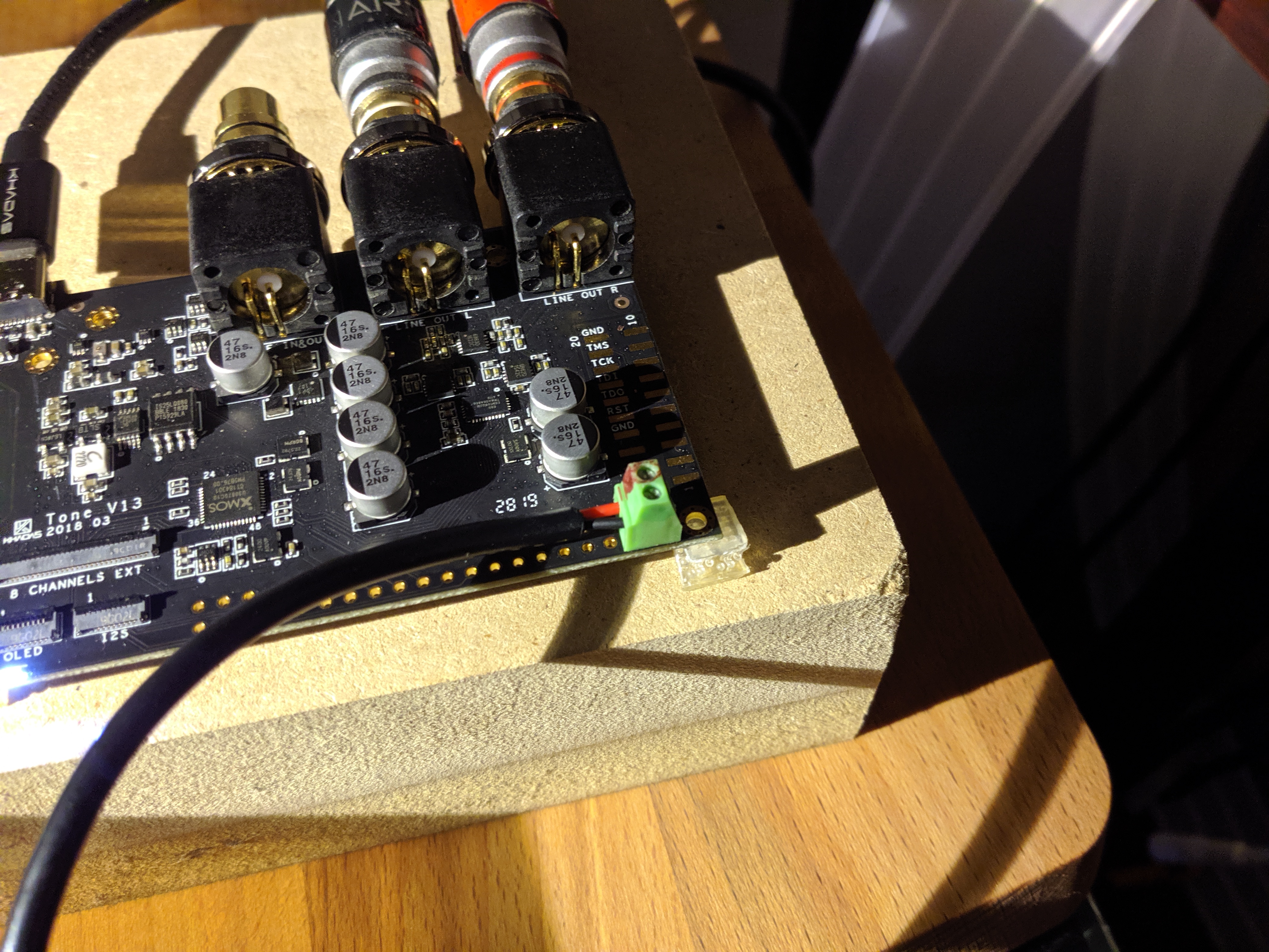
Look at the TB schematic for answers. Power from the USB-C socket (DCIN_VBUS) is used as a signal by U12 to switch the USB data connection to the XMOS between the USB-C socket and the GPIO header input. You need 5V on the USB-C for its data connection to be used. Diodes D1 and D2 prevent either ‘5V’ supply backfeeding into the other, but there’s no formal switching - whichever is the higher voltage ‘wins’. In your case the easiest option is to get a USB B connector to wire to the GPIO header USB data connection, while supplying power from your linear supply to the GPIO power pins.
Incidentally I just noticed there are no resistors on the USB-C CC1 and CC2 pins. This will probably prevent a USB C to C connection working because there’s no indication to the host that a device is connected.
3 Likes
I made my own connector between phone and TB. With power on pins 1 and 21 the USB +5V wire is still needed, the 0 wire is not needed. So only three of the USB wires need to be connected for USB input with external power.
2 Likes
Thank you!!!
I can not implement what you are saying by myself but I hope I’ll get some help to try it!
I guess that now it makes sense to me! From what I can understand!!
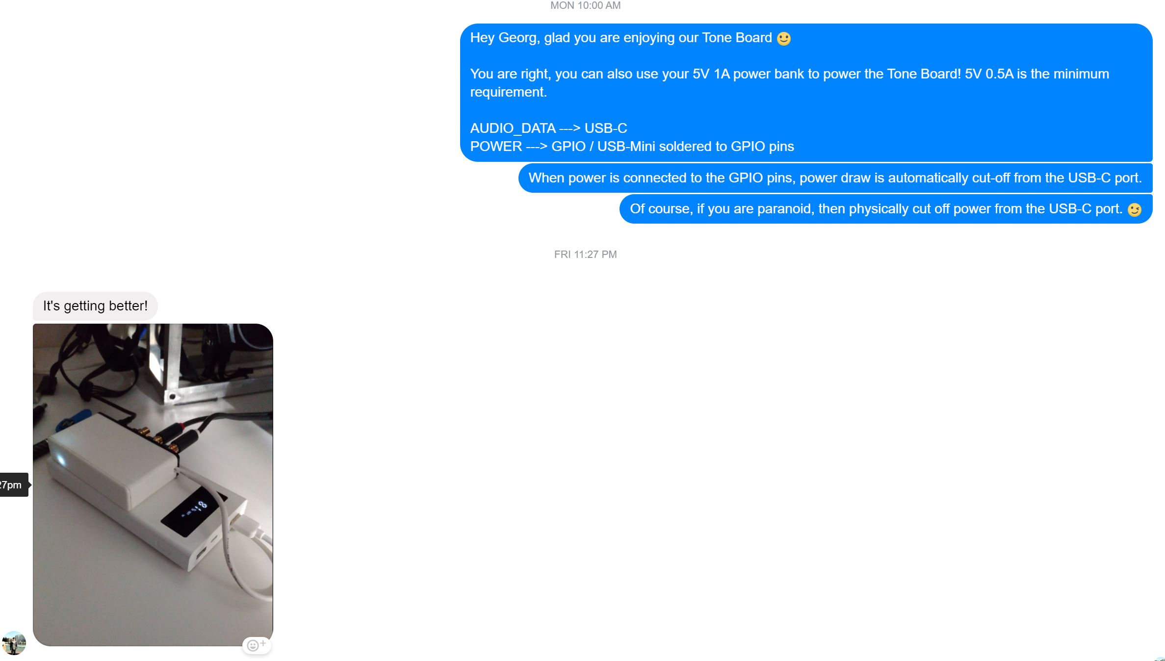
I was communicating with one of our Tone Board users on Facebook. He took the extreme method of powering his Tone Board using a power bank. I did not put this into the original blog post, because it seemed to me that (a) poorly-designed power bank circuits could be noisier, or (b) it would be inconvenient to use a power bank for long periods of time. 
Hi All,
I am investigating how to power the generic tone board from a good power supply directly on the card and keep up as bridge from RPI (not through Y cable which I already manage).
I am confused on what to do to feed power. I understand it is through pin 1 and 21 as presented in this thread, here and on examples on picture here.
However, here it is also mention that a ship needs to be to de-soldered.
What is the exact method? Need to de-solder? Actually what is the purpose of this ship.
Thanks fro you help.
No need to desolder anything. Just solder the 5V DC + and - wires to pins 1 and 21. Works fine!
Hi JaapDeventer.
Thanks a lot. And for the normal UBS-C audio signal, it has to be modified as I see you by cutting the ground cable. Is it correct?