I tried to un-solder SPDIF connector and make direct connecton with dsp output instead. Somehow I managed to damage those 2 tiny rings where SPDIF connector was inserted and soldered to. Can someone point me to pins that represents SPDIF input on board somewhere so I could still make that connection with cable?
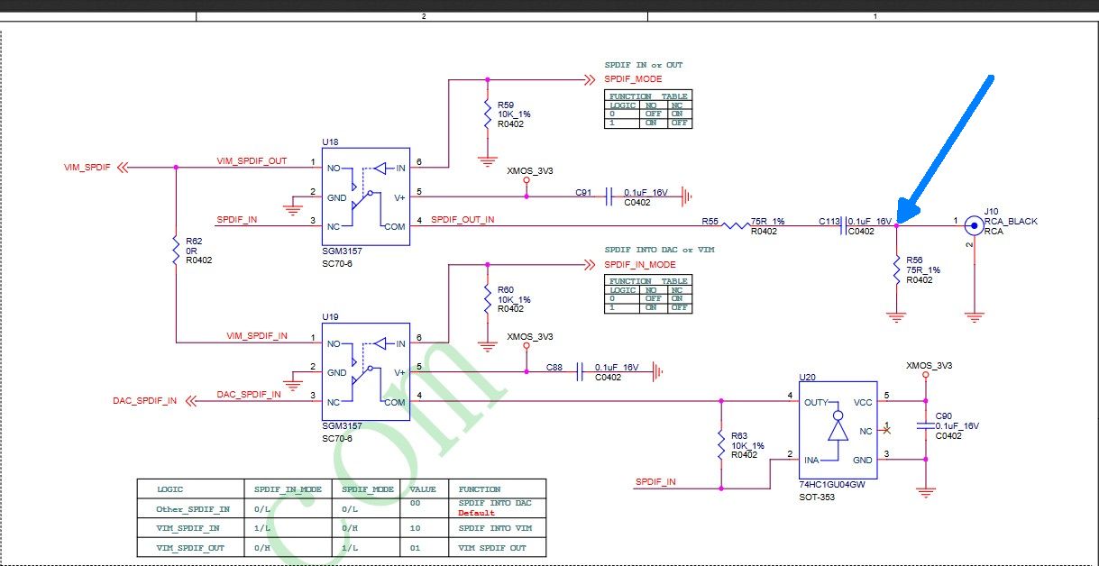
Looking at the tone board schematic and there are couple called SPDIF
would that be SPDIF_IN_MODE - pin16 + pin17 as ground or maybe VIM_SPDIF - pin13 as hot and pin 14 as ground?
The Tone Board has a logic that determines SPDIF routing. Depends on whether the TB is used as a standalone or mounted to a VIM SBC.
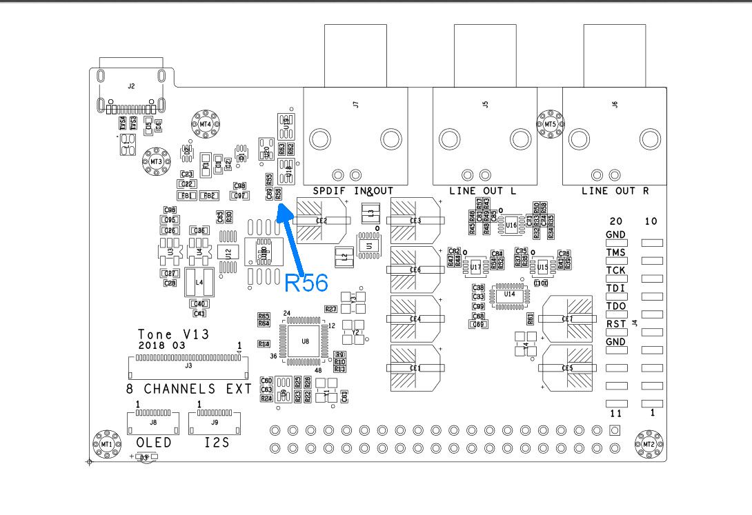
After looking at the TB schematic’s SPDIF section, the junction between R56 and C113 is electrically the same as the SPDIF jack’s center pin. if you could connect a lead to that junction, the lead should function the same as the jack itself. In other words, as it did before your mod.
SPDIF input is available elsewhere, however, input elsewhere will be effected by the TB’s SPDIF switch logic and would require a workaround. that may be as simple as powering over GPIO as opposed to USB-C. I am not solid on this info regarding the SPDIF switch. I will try to study it further. The answer is in the schematic ref the switch logic.
One end of R56 is tied to ground, so it should be easy to determine which end of R56 to attach the lead. Junction of R56 and C113 indicated here…
As you have found out, caution needs to be adequate to prevent damaging the PCB. These boards, like most modern PCBs, can be easy to damage with excessive heat, or attempting to lift a component who’s solder is not fully molten.
Good luck. Keep us posted.
I feel your pain, any electronics engineer will have learnt this Iesson (I know I have) I don’t know what experience you have with electronics but it does beg the question why didn’t you just direct tap off the actual SPDIF connector from the board? I don’t want to sound preachy like a particular famous electronics youtuber The best advice is to practice on dead or donor boards, you will appreciate the process and considerations to be made try an old PC mother board and remove the VGA/USB socket as an example without damaging the multilayer board.
Some of the time it is easier to destroy the connector so you can clear those pads, I hope you can salvage the TB for me it would be an expensive error and the sweet sound of the TB would be silent forever.
 The best advice is to practice on dead or donor boards, you will appreciate the process and considerations to be made try an old PC mother board and remove the VGA/USB socket as an example without damaging the multilayer board.