Which ones GND1-9 ?
Is it a good way to power a standalone tone board from these pins ? it’s not a problem i think, because tone board mounted on a vim1 is powered through exactly these ones.
Best regards, Marco
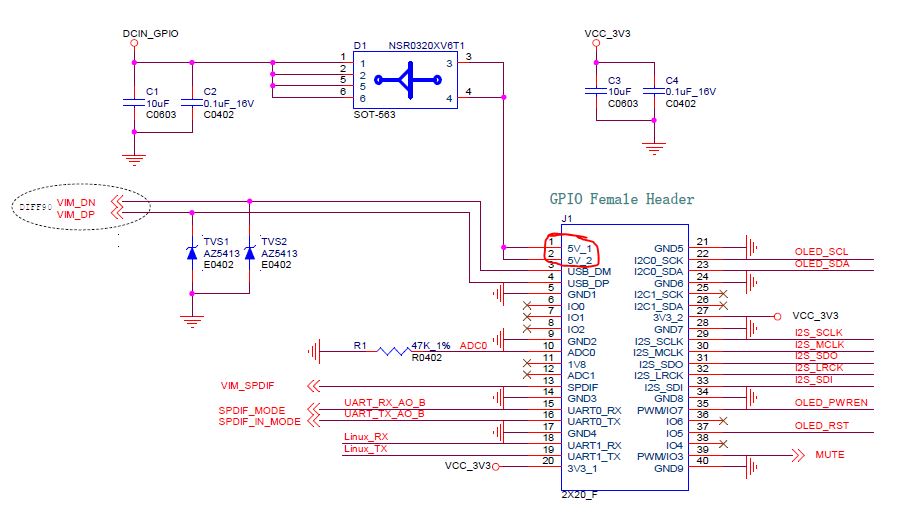
Hello, Any of the pins labeled GND(1-9).
The limit on drawing power from the GPIO is the 5 volt pins are limited to 500mA.
Tone board can draw up to 500mA. Any of the GPIO 5 volt pins and GND(1-9) pins could supply the Tone 5 volt power.
The Generic Tone board is supplied with unmounted GPIO header. It is my understanding that the unmounted headers are the only difference between the two Tone versions.
Refer to Tone board schematic to see which pins are used when Tone is mounted to VIMs.
thanks for your reply,
I thought there was a preferred Ground pin for the power supply. I know that any of gnd(1-9) are elettrically connected, but at PCB design level there could be some differences ( track thickness, for example).
But if all GND(1-9) pins are connected to a ground plane, there’s no difference at all. Is this one the condition of tone board ?
When I connected a USB camera to the GPIO I used pin 5(GND) and pin 2(5v) for power. You will notice between these pins is the USB DM and DP pins. Tone schematic view of GPIO shows connection to these pins, while the VIMs second GPIO USB(DM-pin 7 and DP-pin8) show as no connection to the Tone.
I think it would be safe to use pins 2(5v) and 5(GND) to get the 5 volts for the Tone.
I do not think Khadas offers the silk view of the Tone, as such, I don’t know about traces or how GND pins are tied together.