Congratulations on getting the Edge boards finished, tested and out; I see from the tracking widget that the board I ordered to test is wending its way towards me as I type this.
I’m designing this SoM into an larger piece of kit, doing our own carrier board. Given that I’m doing the work anyway, I thought I’d publicly post an Upverter/Altium part (footprint + symbol for the MXM314 socket with the all the pins correctly labelled for the Edge pin out), and similarly for Kicad.
I’ve done the time-consuming bit already: footprint for the socket, then labelled and double-checked every pin. The final detail is the correct position for the mounting holes, which it’d be really handy to confirm with you. I don’t want to post a footprint that turns out to be wrong!
Say the holes for the big and little plastic alignment pins for the MXM314 socket are at (0, 0) and (82, 0) respectively, on a mm grid. What would the coordinates of the two mounting holes for the Edge be? I think from crude measurements of the silkscreen drawings that they’re somewhere around (18.9, 47.5) and (63.1, 47.5) but it would be really useful to confirm. Are they for an M2.5 or an M3 screw?
Sorry, hard to word the question I’m asking simply! Basically, I’m just asking for the coordinates of the mounting holes on the Captain board, but I need to know where the origin is in relation to the MXM3 socket too, e.g. what the position of that socket is in those coordinates.
I measured from the Captain DXF file. In case anyone else needs the locations of the mounting holes, they’re 47.5mm out from the line through the mounting holes of the MXM314 connector, and 44.2mm apart, their mid point in line with the midpoint of the mounting holes.
(These measurements are within 0.01mm or 0.02mm, anyway. For some reason, the locations don’t seem to lie on an exact grid in the DXF file, nor even on an exact grid relative to one another.)
May I know that if the PCB file as Allegro format works you or not? I can share the Captain PCB file(only keep the MXM3 connector and the mount holes) if it works you.
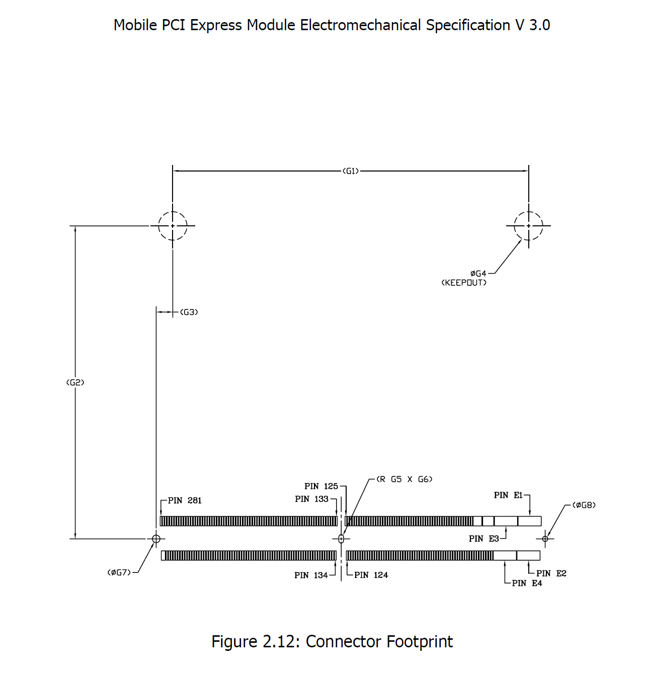
We will release a document as below, but need more time to complete:
Hi Gouwa, that’d be brilliant, many thanks. I think I might be able to read or import Allegro format in Kicad - never tried - but failing that, I could always read the coordinates off a Gerber export of the Allegro file?
Would you mind leaving the location of the I-IPEX wifi/bluetooth ‘fingers’ on too, so I can make sure I include those in my footprint for other designers who might want to use them? I’m keen to make a useful footprint and design drawing so other people can create projects to drop Edge boards into without having to do lots of research and detailed measurement.