I2S Input options

Hello,

I would like to know if the tone board is capable to be used as stand-alone DAC (no VIM or other SBC for controling) just I2S in -> analog out) with I2S Input?
I guess it is driven in async mode, so no MCKL signal is needed, correct?

Which board Version would be recommended to use it as I2S or as SPDIF stand-alone DAC?
Where is the I2S signal (DATA, BCKL, LRCKL, GND) to be connected to the board (8 channel Extension or other connector)?

Which I2S format is necessary (thinking of connecting it to a nanoSHARC miniDSP board)?

Thank you!

1 Like

Hi Freezebox:
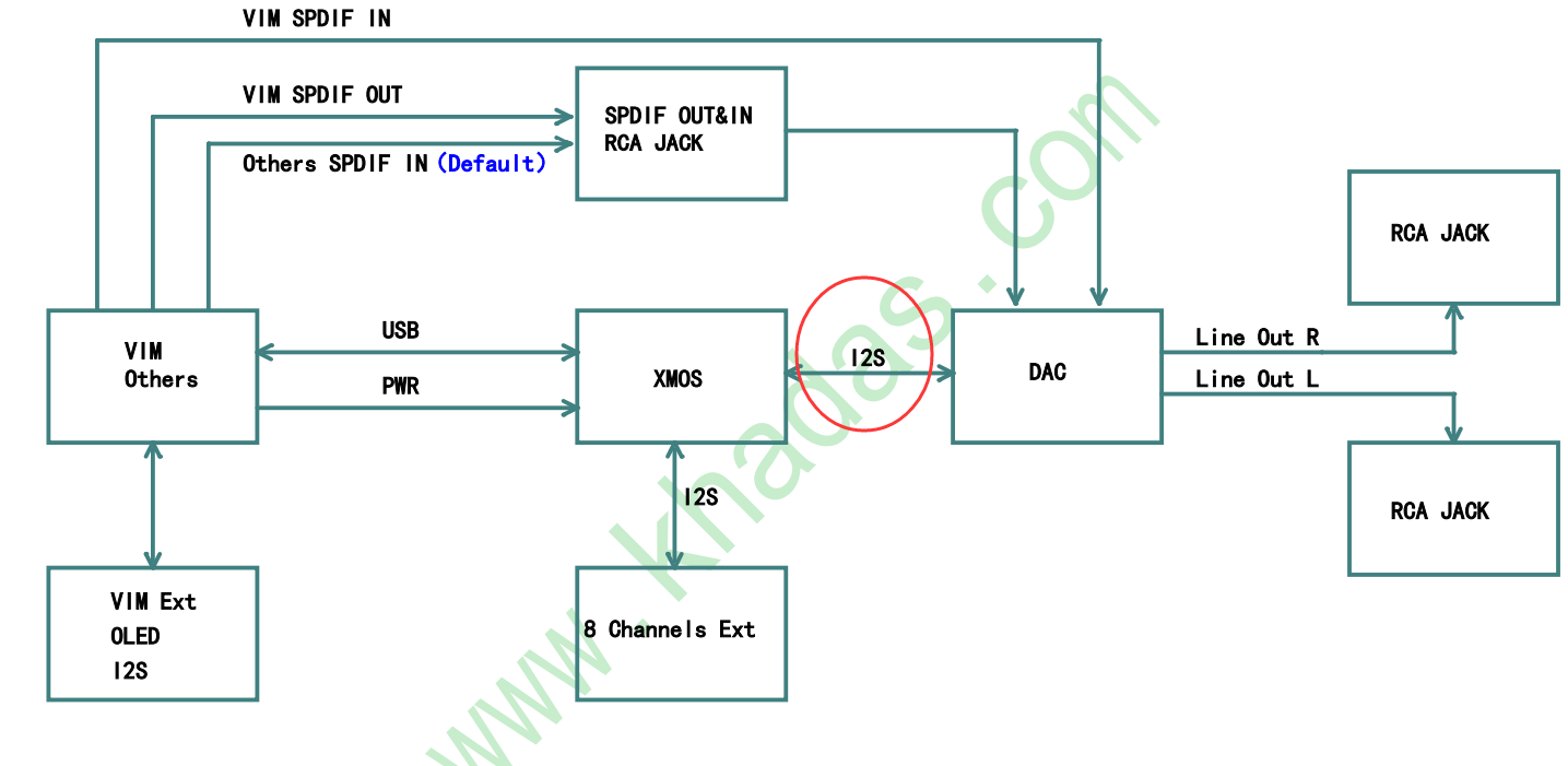
Yes, the Tone Board can also work as stand-alone DAC. Actually, the Tone Board digram as below:

And the I2S interfaca is available on the 30PIN FPC connector showed as below:

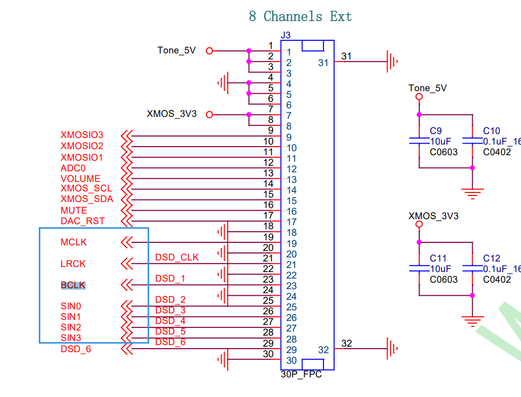
The Schematic is available at Khadas Download.

Have Fun!

2 Likes

Thanks Gouwa! This is good news!

so better VIM or Generic tone board version for stand alone DAC application?

external MCLK is not necessary, right?

SIN0 … SIN3 are I2S DATA signals from external source, right? So would following connection work from external I2S source?

21 LRCK
23 BCLK
25 DATA
24 GND (e.g.)

which FIR filters are set at DAC output by default?

Thanks!

1 Like

I think Generic version should be better for you.

Needed, as the ES9038 work as slave mode.

Yes.

You can check ES9038 Datasheet for the details

Have fun!

1 Like

es9038q2m can run in async mode, so MCLK would not be needed as you have crystals on the board, no? How do you handle I2S input from Raspi that also does not supply a MCLK signal?

Btw. could I also use pin 29, (30), 32 and 33 of the 40pin GPIO as I2S input for stand alone DAC? The 30pin FPC frankly is not very handy for DIY…

the only plugin yet available for the nanoSHARC drives only four of the output channels, so you wouldn’t get the full 8 channels from that DAC board.
9Apps Lucky Patcher

Hi,

Are there any other requirements to get the tone board to work as a stand-alone i2s dac?
I’ve tried the following connection with my nanoSHARC dsp:

J5 to 30 pin FPC
3 GND to 18 GND
4 MCLK to 19 MCLK
1 I2S_LRCLK to 21 LRCK
2 I2S_BCLK to 23 BCLK
5 I2S_OUT0 to 25 SIN0

nanoSHARC i2s pinouts can be found on page 10 of the manual:

With this config I didn’t get any output from the TB. I powered the TB using a usb phone charger.

Please advise,
Thank you

According to the scheme, the MCLK on the “8ch expansion” port of the TB is only connected to the XMOS, not to the DAC. Is it meant as output only?

The I2S from the GPIO header is only connected to the I2S expansion port. It is not connected to anything else on the TB, so it probably cannot be used as input.

…wonder if some admin from Khadas is reading this thread - waiting for an answer since beg of october… not what I call responsive frankly.

wonder if we’ll get a reply this year :upside_down_face:

Hello, I am bit out of my element on this topic. I recall reading if the Tone Board is powered by USB, the board assumes USB for input. While I do not know if what you want to do is possible, maybe powering from GPIO will produce something.
Good luck, hope you find the answers you seek.

Powering the TB through the GPIO will only switch the XMOS USB input from the USB-c port to the USB pins on the GPIO. That is all.

Only the I2S on the expansion connector exposes the I2S connection between the XMOS and the DAC (adding the rest of the 8 channels and the I2C bus used to control the DAC).

I have no idea whether the XMOS will make problems if you use this point as input and “interfere” directly into the communication between the XMOS and the DAC. You can always just “cut off” the XMOS - physically with a knife or by clearing the firmware? ;-). But I see no point in discarding half of the ToneBoard - if you want to use I2S input only, it is better to buy another board with the DAC only and not the Khadas TB with the XMOS USB Audio adapter. For example, the Audiophonics DAC card is made for I2S input only and (instead of the XMOS USB-to-I2S controller) it adds its own custom chip to adapt the DAC better to any possible I2S input, so it could be easier to use for such purpose. However, it is not any cheaper at all.

2 Likes

For me the issue was finding an i2s input DAC board that has well documented measurements. The TB was the only DAC I could find that had been measured and proven to perform well for a reasonable price. The initial posts in this thread led me to believe it could be used as a standalone i2s DAC.

Cheers

1 Like

I see. Thanks for clearing that up for me.

Hi Gouwa,

I want to use my Raspberry Pi with the HiFiBerry Digi+ Pro to connect to my Tone Board. The Digi+ Pro has an i2s output which is as follows:
GND
MCK
BCK
LRC
DATA

I want to know if I can connect the Tone Board with these inputs. And, if possible, how to connect the Digi+ pro to the GPIO of the Tone Board?

If not possible with the GPIO, can the 30 pin fpc be of any help connecting these two devices with i2s?

With kind regards,

Thomas

You want the SPDIF output feature of the HiFiBerry Digi+ Pro, right?

Actually, the I2S on the 40 PIN GPIO is pinout from the VIMs SBC, no it will not work if only with Tone Board.

Yes, the I2S of ES9038Q2M is available on the 30PIN FPC connector, so it should be no problem.

Have fun!

1 Like

Regarding the I2S fpc connector, was wondering if its possible to have that connected to a I2S source while also connected to USB input?

If yes, would there be a need to switch between the 2 sources? And if yes, would like to know how to actuate that.

Thanks.

Dear @Gouwa,

I want to connect the P4 header (i2s output) of my HiFiBerry Digi+ Pro to the i2s input of the ToneBoard.

Header P4 looks as following:
1: Ground
2: Master clock
3: Bit clock
4: Frame clock
5: Data output

If I look at the schematics of J1(the 40 pin-out header of the ToneBoard) I found the following.
28: Ground
29: Bit clock
30: Master clock
32: Frame clock
33: Data input

Can this configuration work? I do not want to use the J9 i2s input but only the J1 header. Also I want to be sure that it works because soldering on the Digi+ Pro voids the warranty :confused:

Hi Thomas:
As the I2S signals of J1(40PIN Header) is connectted to the CPU of the VIM1/2 boards, so I don’t think it will work out.

The I2S Input of the Toneboard is available on J3 FPC connectors, you can check the schematic for the further details.

Have fun!

hi. was anyone able to use input i2s and get something? i’m interested.

1 Like