for my 4-Way active speaker project I have bought four Khadas Tone1 boards to place two each into each boxes’ electronics near the power amps inputs.
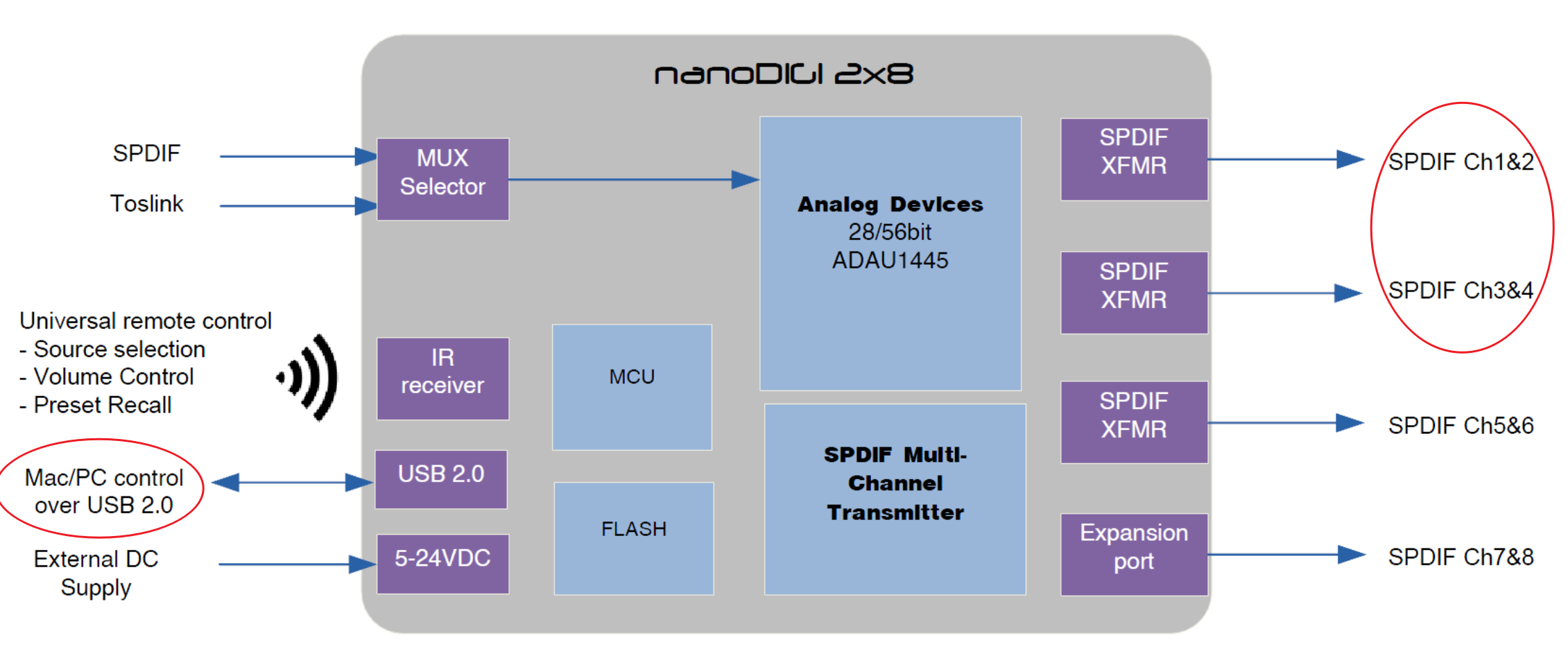
The original idea was to have two SPDIF cables running from a nanoDIGI, so each Tone board would have its own connection.
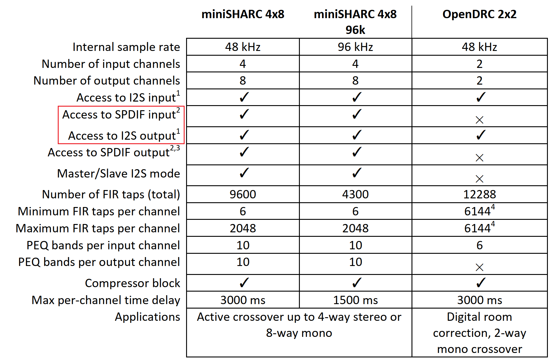
In the mean time I have found out that a miniSHARC would suit my project better than a nanoDIGI and that the Tone1 supports I²S.
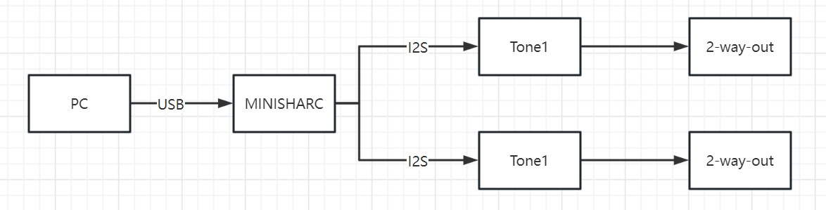
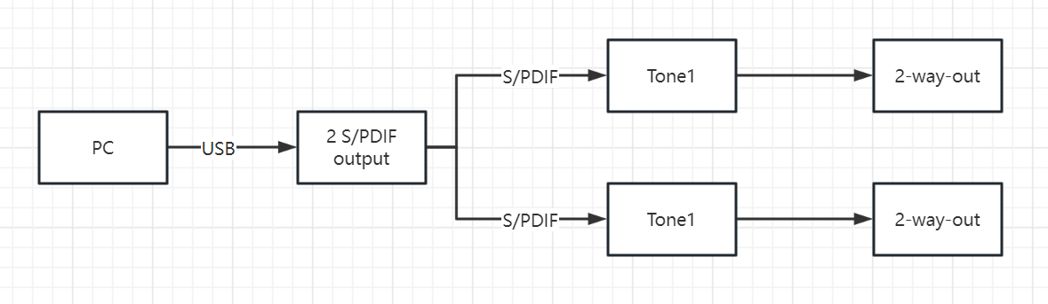
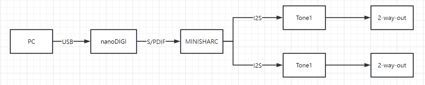
The latest idea is now to try and place one miniSHARC board and two Tone1 boards in each boxes’ electronics. This way one SPDIF cable would feed each boxes’ miniSHARC-digiFP input and its I²S outputs could be feed the Tone1s.
My Questions:
IS this possible with plain Tone1 (not VIM!) in standalone mode?
How do I implement this configuration?
thanks a lot for the overwhelimg and extensive response!
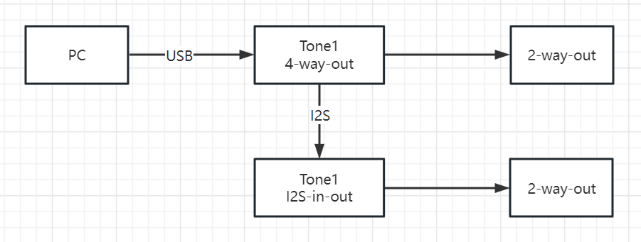
After glancing over the options it seems like option 2 would most suitable for my implementation! I had obtained four Tone1s already, soldering is not a hrudle and I’m aware of the need for shortest I²S connection needs! I’m very happy to see a solution not needing a firmware tweak!
I’ll be back when thi implementation works or if I need further support
Thanks and Regards,
Winfried
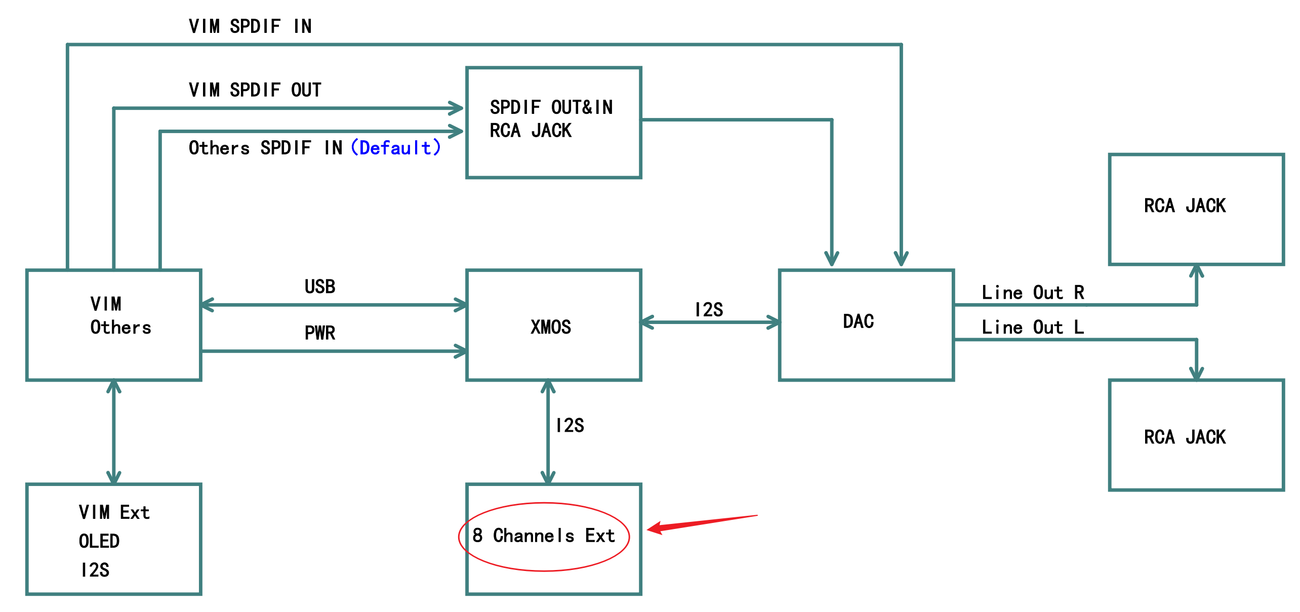
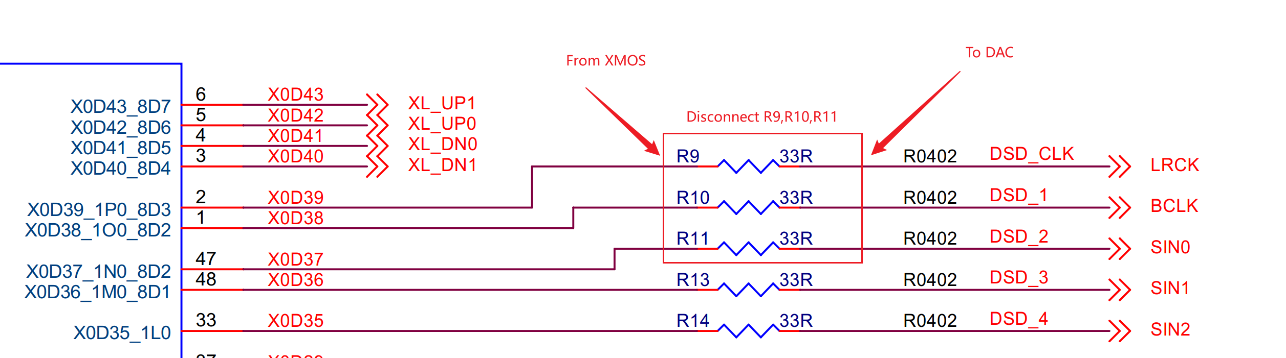
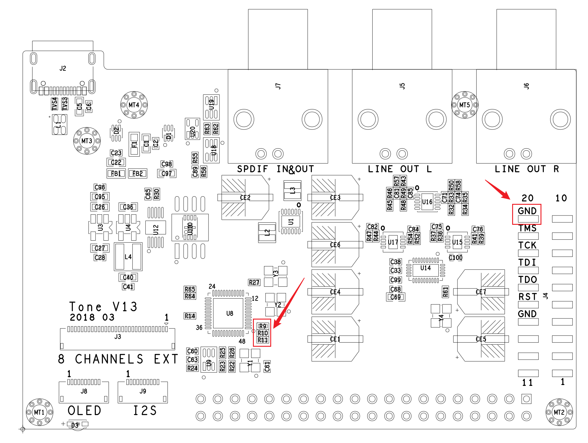
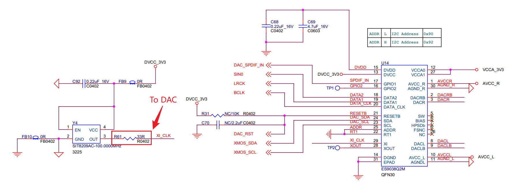
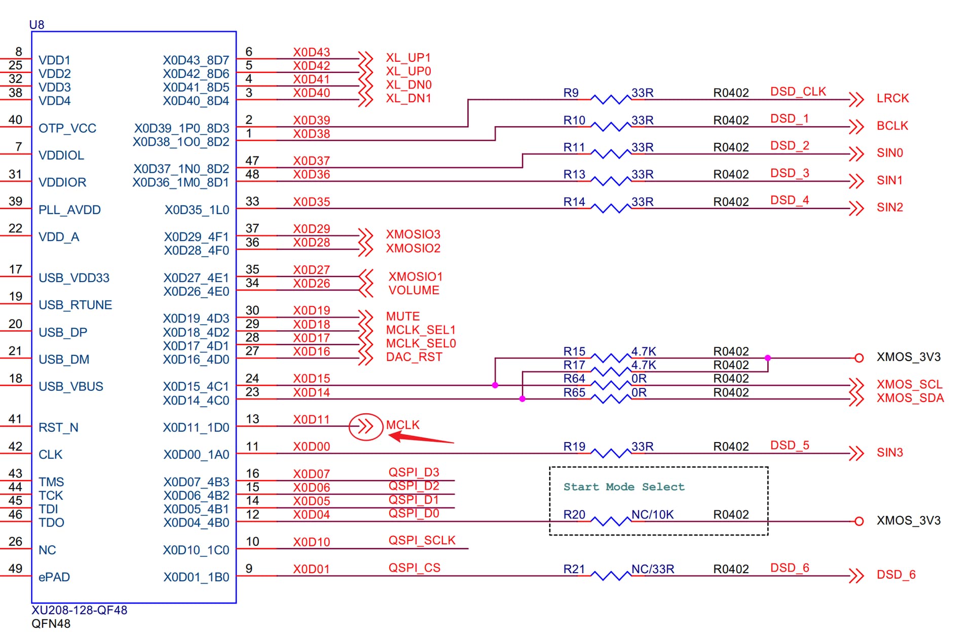
The signal on the left side of the resistor comes from XMOS, and the signal on the right side of the resistor goes to DAC. Disconnect this resistor and connect the right side to the miniSHARC. also need a GND to the miniSHARC.
This Info really helps! The only concern left is the sync between the miniSHARC‘s and the DACs‘ individual 24.576MHz clocks.
Would it be beneficial or detrimental if one central Oscillator fed all three devices?
BTW: My Datastream will be either 24/48 or 24/96 Resolution, so only 24.576MHz will be in use, resampling of CD 16/44 is done separately.
Hi Winfried,
I’m not sure if a clock passing through a jump wire would be better. Generally speaking, the crystal oscillator source needs to be routed close to the chip, and being too far away from the chip may have an impact.
Currently, Tone1’s DAC operates in asynchronous clock mode, using a 100M crystal oscillator. THD+N is approximately 2dB lower than synchronous clock.
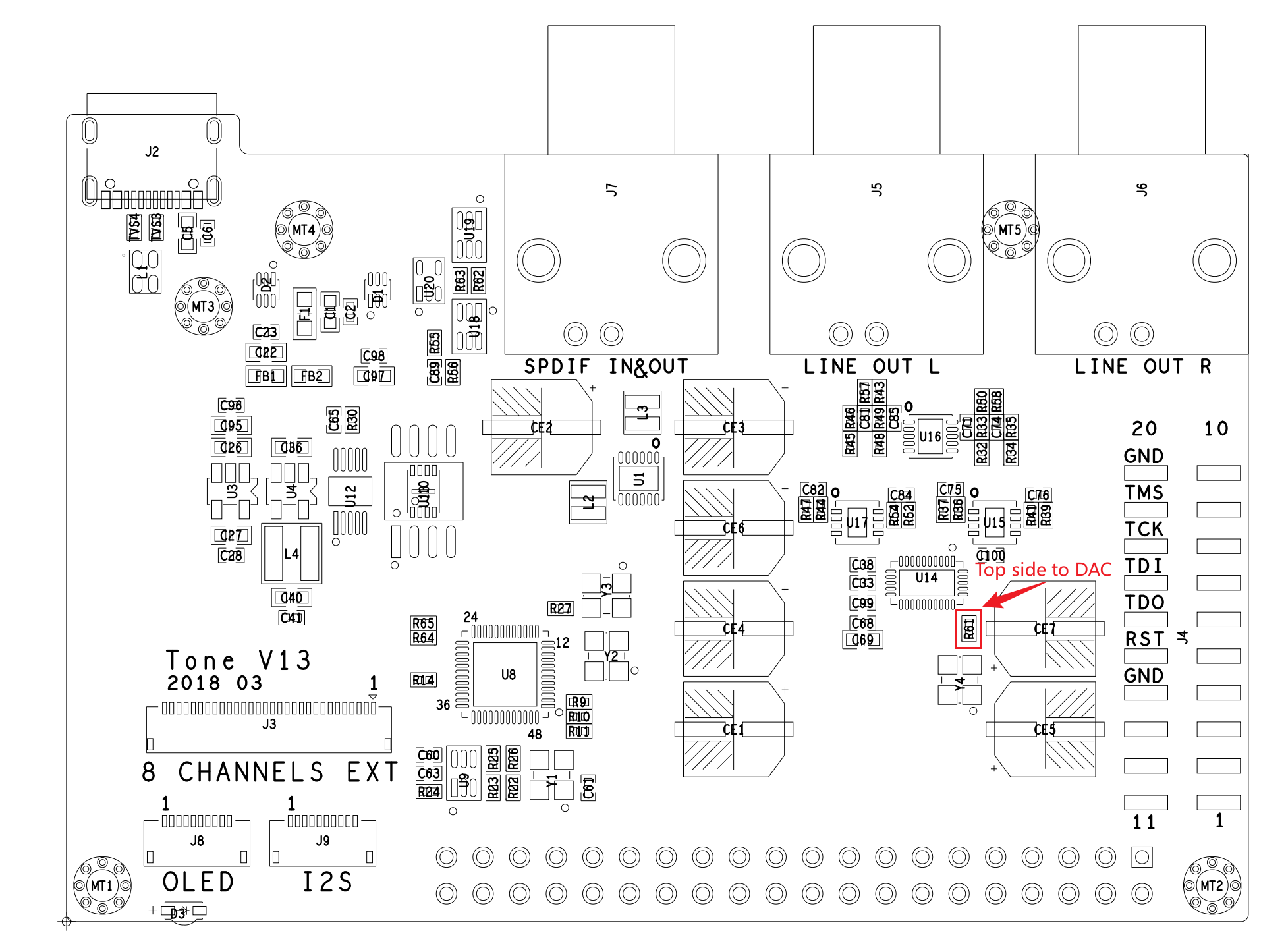
If you want to try using synchronous clock mode, you can disconnect R61 and solder the miniSHARC‘s clock to the top side of the resistor.
After looking through the Tone1 Schematic I’m a bit confused and hope you will patiently resolve that
Page 5 of the Tone_V13_Sch.pdf shows 22.5792 and 24.576MHz oscillators obviously selected by MCLK_SEL1 and MCLK_SEL0 enabling signals. From your statement “…Tone1’s DAC operates in asynchronous clock mode, using a 100M crystal oscillator…” it seems as if these oscillators are not used by the DAC!
By the way: My idea had been to lift the left side of R27 and feed a Tent Clock 24.576MHz low jitter signal signal into it (the I²S input signal will always be 24/48 or 24/96!). Another Output of that Clock generator is/was planned to substitute the 24.476 MHz clock circuit of the miniSHARC, so that both the DSP and the DAC work off the same clock!
What am I missing or getting wrong here?
Thanks and Regards,
Winfried
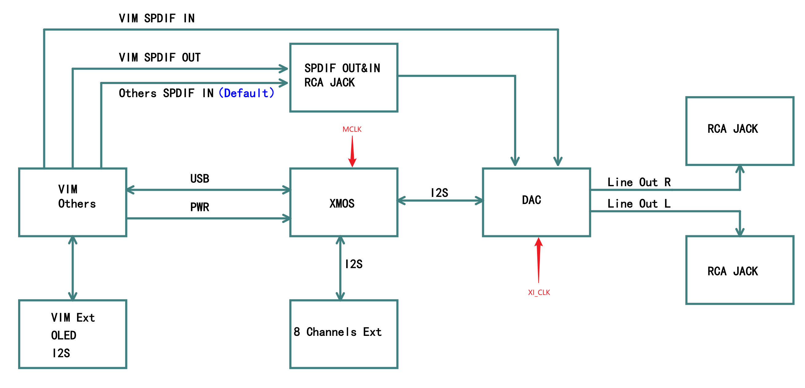
Yes, the clock is for XMOS (XMOS will decode the USB data to I2S, as your device miniSHARC function), not for the DAC. For your application scenario, you have used miniSHARC instead of XMOS, so there is no need to modify R27.
OK!
This helps, but USB will not be the audio input in this (digital cross over) application anyway and maybe this did not come out clearly enough so far
To make sure the desired functionality works, I plan to proceed in steps:
use SPDIF as miniSHARC to Tone1 connection through a nanoDIGI (or DIG-FP)
When 1. works (because the distance between miniSHARC and Tone1 is so short, i.e. ~ 5 centimeters anyway) I want to circumvent the then unneeded SPDIF (coding, driving, transformers, connections, cables, transformers, decoding) by direct I²S connections.
The “synchronous” clocking of the driving miniSHARC and the two Tone1s from one 24.576MHz clock source with 3 drive outputs (instead of the three respective on-board oscillators) would be the desired “icing on the cake”. In this respect your hint at synchronous DAC mode implementation is very helpful!
In any case: External Audio input is only to miniSHARC (SPDIF or AES/EBU) input anyway, no direct USB audio gets to Tone1 (USB>SPDIF conversion is done further up in the digital signal chain).
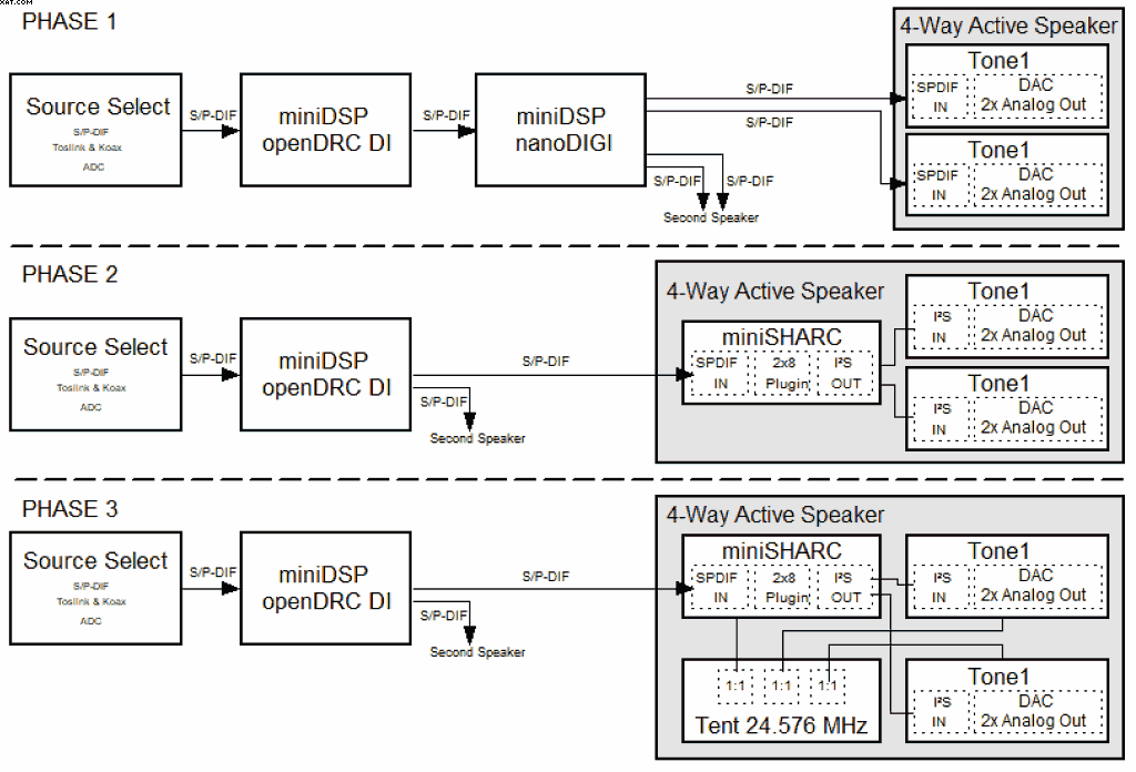
Phase 1 is for testing and inital listening, the nanoDIGI will feed the Tone1s with SPDIF cabling
Phase 2 is for more powerful DSP and implements miniSHARC in the box together with the Tone1s (first with short SPDIF and then hopefully short I²S)
Phase 3 is for synchronising all three clocks in the 4-way box and the final set up if I can make it work. If this does not work the fall-back is Phase 2.
So there is not any USB to SPDIF or USB to I²S conversion, this happens ahead of the pictured chain (if necessary…).
Just thought of a question I probably should have asked earlier: When using I²S one of the involved circuits should/could be clock master. As miniSHARC is (logically?) a clock master with his 24.576MHz clocking, how would it be possible to make the Tone1 an I²S clock slave?
I’m asking because it seems to me like master/slave clocking may make implementation easier, more straight forward…(?)
Thank you for your patience with my limited competence…