Project Introduction
The project involves managing and controlling various hardware components using GPIO (General-Purpose Input/Output) pins on a microcontroller or single-board computer. These components include relays, dry contacts, and other peripherals that require precise control through GPIO interfaces.
Understanding the Issue
- Mapping Confusion:
- The issue seems to involve a mismatch or confusion between GPIO pin names and their corresponding pin numbers or mappings.
- Backend Crash:
- The backend crashes when dealing with the
Relay2pins, which could be due to improper handling of GPIO mapping.
Actual Result
here are the pins that we are using:
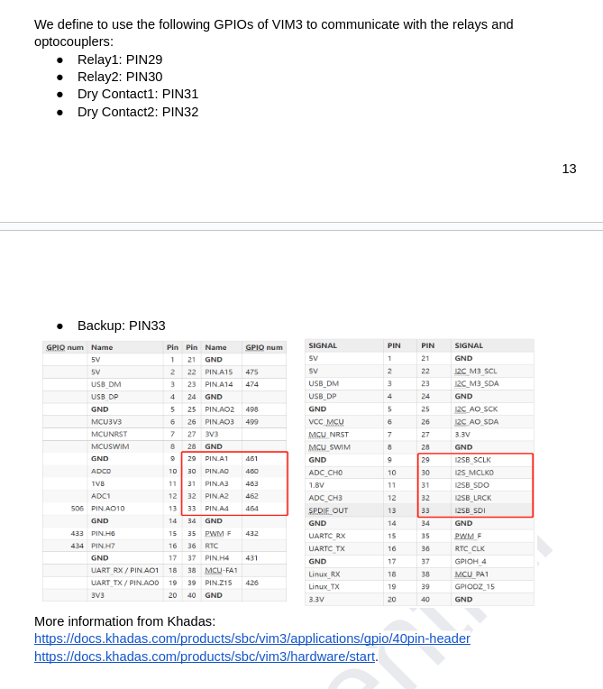
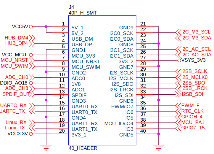
here is the khadas documentation:
schematics
meson-g12a-gpio.g_
/* First GPIO chip */
#define GPIOAO_0 0
#define GPIOAO_1 1
#define GPIOAO_2 2
#define GPIOAO_3 3
#define GPIOAO_4 4
#define GPIOAO_5 5
#define GPIOAO_6 6
#define GPIOAO_7 7
#define GPIOAO_8 8
#define GPIOAO_9 9
#define GPIOAO_10 10
#define GPIOAO_11 11
#define GPIOE_0 12
#define GPIOE_1 13
#define GPIOE_2 14
/* Second GPIO chip /
#define GPIOZ_0 0
#define GPIOZ_1 1
#define GPIOZ_2 2
#define GPIOZ_3 3
#define GPIOZ_4 4
#define GPIOZ_5 5
#define GPIOZ_6 6
#define GPIOZ_7 7
#define GPIOZ_8 8
#define GPIOZ_9 9
#define GPIOZ_10 10
#define GPIOZ_11 11
#define GPIOZ_12 12
#define GPIOZ_13 13
#define GPIOZ_14 14
#define GPIOZ_15 15
#define GPIOH_0 16
#define GPIOH_1 17
#define GPIOH_2 18
#define GPIOH_3 19
#define GPIOH_4 20
#define GPIOH_5 21
#define GPIOH_6 22
#define GPIOH_7 23
#define GPIOH_8 24
#define BOOT_0 25
#define BOOT_1 26
#define BOOT_2 27
#define BOOT_3 28
#define BOOT_4 29
#define BOOT_5 30
#define BOOT_6 31
#define BOOT_7 32
#define BOOT_8 33
#define BOOT_9 34
#define BOOT_10 35
#define BOOT_11 36
#define BOOT_12 37
#define BOOT_13 38
#define BOOT_14 39
#define BOOT_15 40
#define GPIOC_0 41
#define GPIOC_1 42
#define GPIOC_2 43
#define GPIOC_3 44
#define GPIOC_4 45
#define GPIOC_5 46
#define GPIOC_6 47
#define GPIOC_7 48
#define GPIOA_0 49
#define GPIOA_1 50
#define GPIOA_2 51
#define GPIOA_3 52
#define GPIOA_4 53
#define GPIOA_5 54
#define GPIOA_6 55
#define GPIOA_7 56
#define GPIOA_8 57
#define GPIOA_9 58
#define GPIOA_10 59
#define GPIOA_11 60
#define GPIOA_12 61
#define GPIOA_13 62
#define GPIOA_14 63
#define GPIOA_15 64
#define GPIOX_0 65
#define GPIOX_1 66
#define GPIOX_2 67
#define GPIOX_3 68
#define GPIOX_4 69
#define GPIOX_5 70
#define GPIOX_6 71
#define GPIOX_7 72
#define GPIOX_8 73
#define GPIOX_9 74
#define GPIOX_10 75
#define GPIOX_11 76
#define GPIOX_12 77
#define GPIOX_13 78
#define GPIOX_14 79
#define GPIOX_15 80
#define GPIOX_16 81
#define GPIOX_17 82
#define GPIOX_18 83
#define GPIOX_19 84/ First GPIO chip */
#define GPIOAO_0 0
#define GPIOAO_1 1
#define GPIOAO_2 2
#define GPIOAO_3 3
#define GPIOAO_4 4
#define GPIOAO_5 5
#define GPIOAO_6 6
#define GPIOAO_7 7
#define GPIOAO_8 8
#define GPIOAO_9 9
#define GPIOAO_10 10
#define GPIOAO_11 11
#define GPIOE_0 12
#define GPIOE_1 13
#define GPIOE_2 14
/* Second GPIO chip */
#define GPIOZ_0 0
#define GPIOZ_1 1
#define GPIOZ_2 2
#define GPIOZ_3 3
#define GPIOZ_4 4
#define GPIOZ_5 5
#define GPIOZ_6 6
#define GPIOZ_7 7
#define GPIOZ_8 8
#define GPIOZ_9 9
#define GPIOZ_10 10
#define GPIOZ_11 11
#define GPIOZ_12 12
#define GPIOZ_13 13
#define GPIOZ_14 14
#define GPIOZ_15 15
#define GPIOH_0 16
#define GPIOH_1 17
#define GPIOH_2 18
#define GPIOH_3 19
#define GPIOH_4 20
#define GPIOH_5 21
#define GPIOH_6 22
#define GPIOH_7 23
#define GPIOH_8 24
#define BOOT_0 25
#define BOOT_1 26
#define BOOT_2 27
#define BOOT_3 28
#define BOOT_4 29
#define BOOT_5 30
#define BOOT_6 31
#define BOOT_7 32
#define BOOT_8 33
#define BOOT_9 34
#define BOOT_10 35
#define BOOT_11 36
#define BOOT_12 37
#define BOOT_13 38
#define BOOT_14 39
#define BOOT_15 40
#define GPIOC_0 41
#define GPIOC_1 42
#define GPIOC_2 43
#define GPIOC_3 44
#define GPIOC_4 45
#define GPIOC_5 46
#define GPIOC_6 47
#define GPIOC_7 48
#define GPIOA_0 49
#define GPIOA_1 50
#define GPIOA_2 51
#define GPIOA_3 52
#define GPIOA_4 53
#define GPIOA_5 54
#define GPIOA_6 55
#define GPIOA_7 56
#define GPIOA_8 57
#define GPIOA_9 58
#define GPIOA_10 59
#define GPIOA_11 60
#define GPIOA_12 61
#define GPIOA_13 62
#define GPIOA_14 63
#define GPIOA_15 64
#define GPIOX_0 65
#define GPIOX_1 66
#define GPIOX_2 67
#define GPIOX_3 68
#define GPIOX_4 69
#define GPIOX_5 70
#define GPIOX_6 71
#define GPIOX_7 72
#define GPIOX_8 73
#define GPIOX_9 74
#define GPIOX_10 75
#define GPIOX_11 76
#define GPIOX_12 77
#define GPIOX_13 78
#define GPIOX_14 79
#define GPIOX_15 80
#define GPIOX_16 81
#define GPIOX_17 82
#define GPIOX_18 83
#define GPIOX_19 84
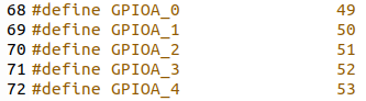
By inspecting the schematics and the meson-g12-gpio.h documents, we conclude that the path path from gpio headers to pins :
GPIO 29 → I2SB_SCLK → GPIOA_1 → pin 50
GPIO 30 → I2S_MCLK0 → GPIOA_0 → pin 49
GPIO 31 → I2SB_SDO → GPIOA_3 → pin 52
GPIO 32 → I2SB_LRCK → GPIOA_2 → pin 51
GPIO 33 → I2SB_SDI → GPIOA_4 → pin 53
An they are all localted on the gpiochip1.
We conclude that the following is the right mapping:
const (
Chip1 = “gpiochip1”
)
// Pin names
const (
Relay1 = 50
Relay2 = 49
DryContact1 = 52
DryContact2 = 51
Backup = 53
)
// Define pin names and their associated chip
var pinMappings = map[string]struct {
Pin int
Chip string
}{
“Relay1”: {
Pin: Relay1,
Chip: Chip1,
},
“Relay2”: {
Pin: Relay2,
Chip: Chip1,
},
“DryContact1”: {
Pin: DryContact1,
Chip: Chip1,
},
“DryContact2”: {
Pin: DryContact2,
Chip: Chip1,
},
“Backup”: {
Pin: Backup,
Chip: Chip1,
},
}
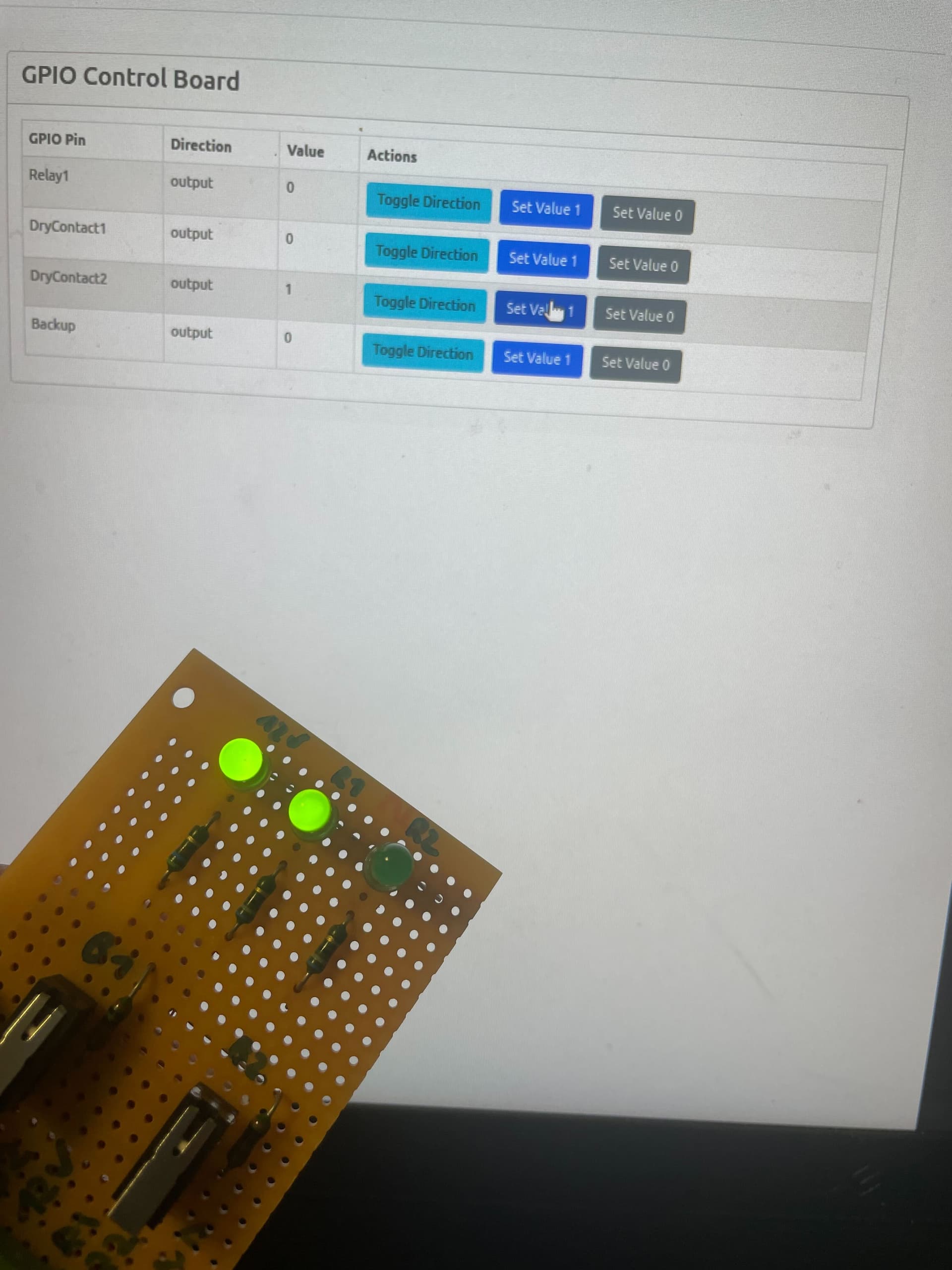
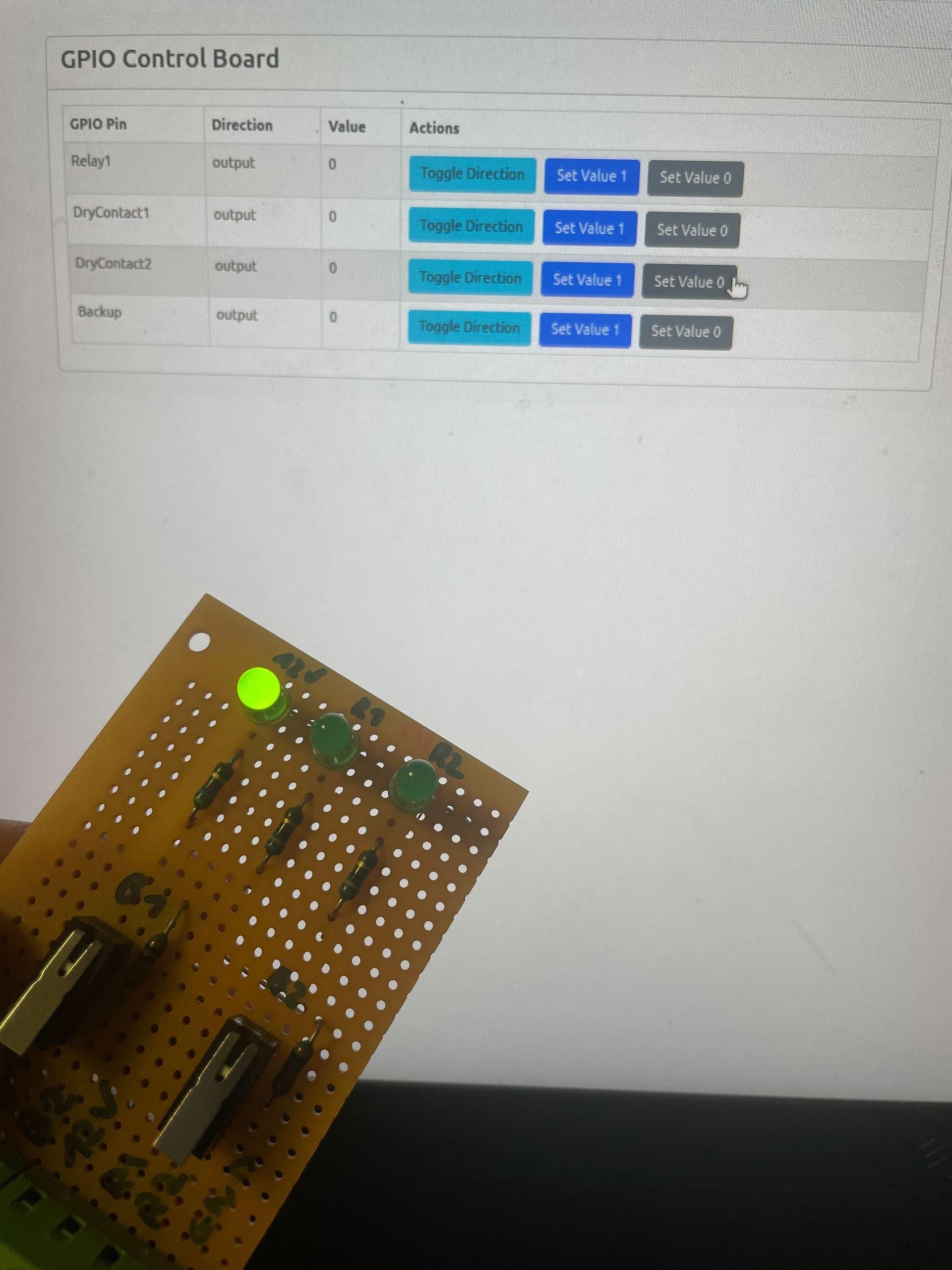
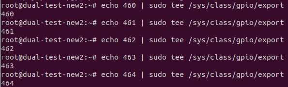
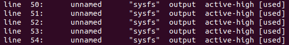
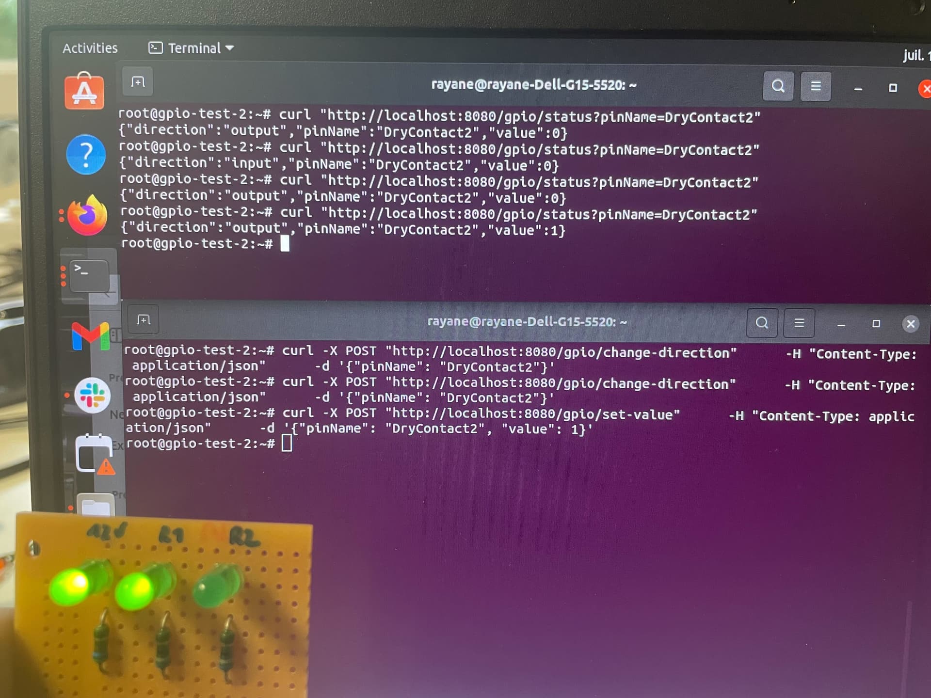
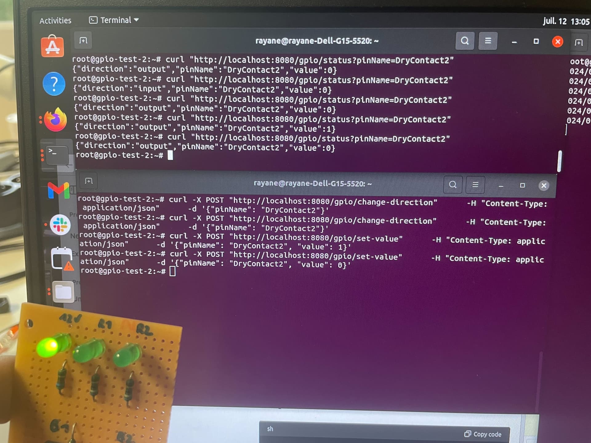
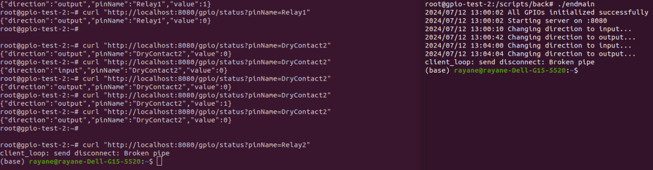
he problem isn’t in how we have wired the pins since it’s correctly working with the sysfs approach:
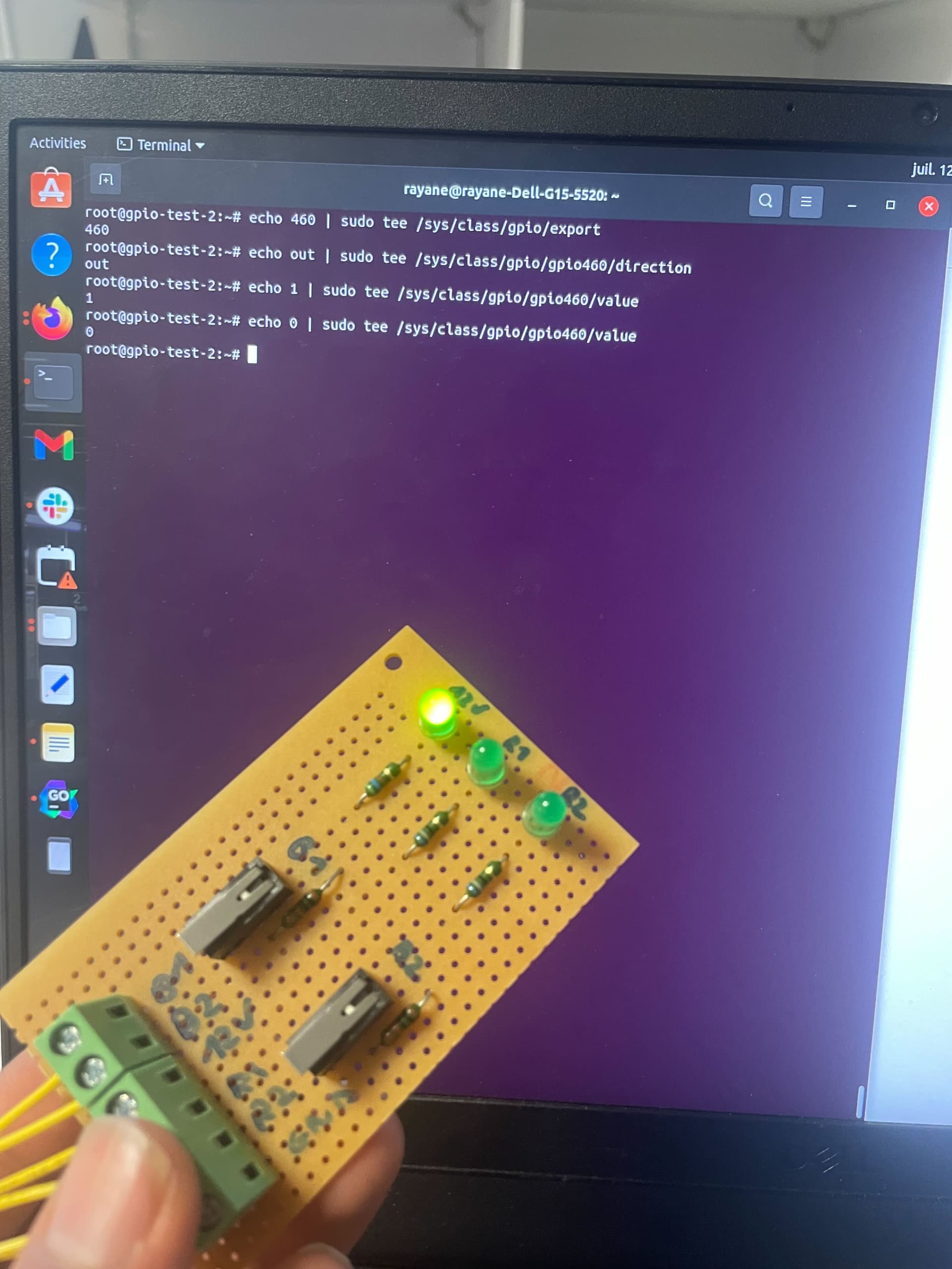
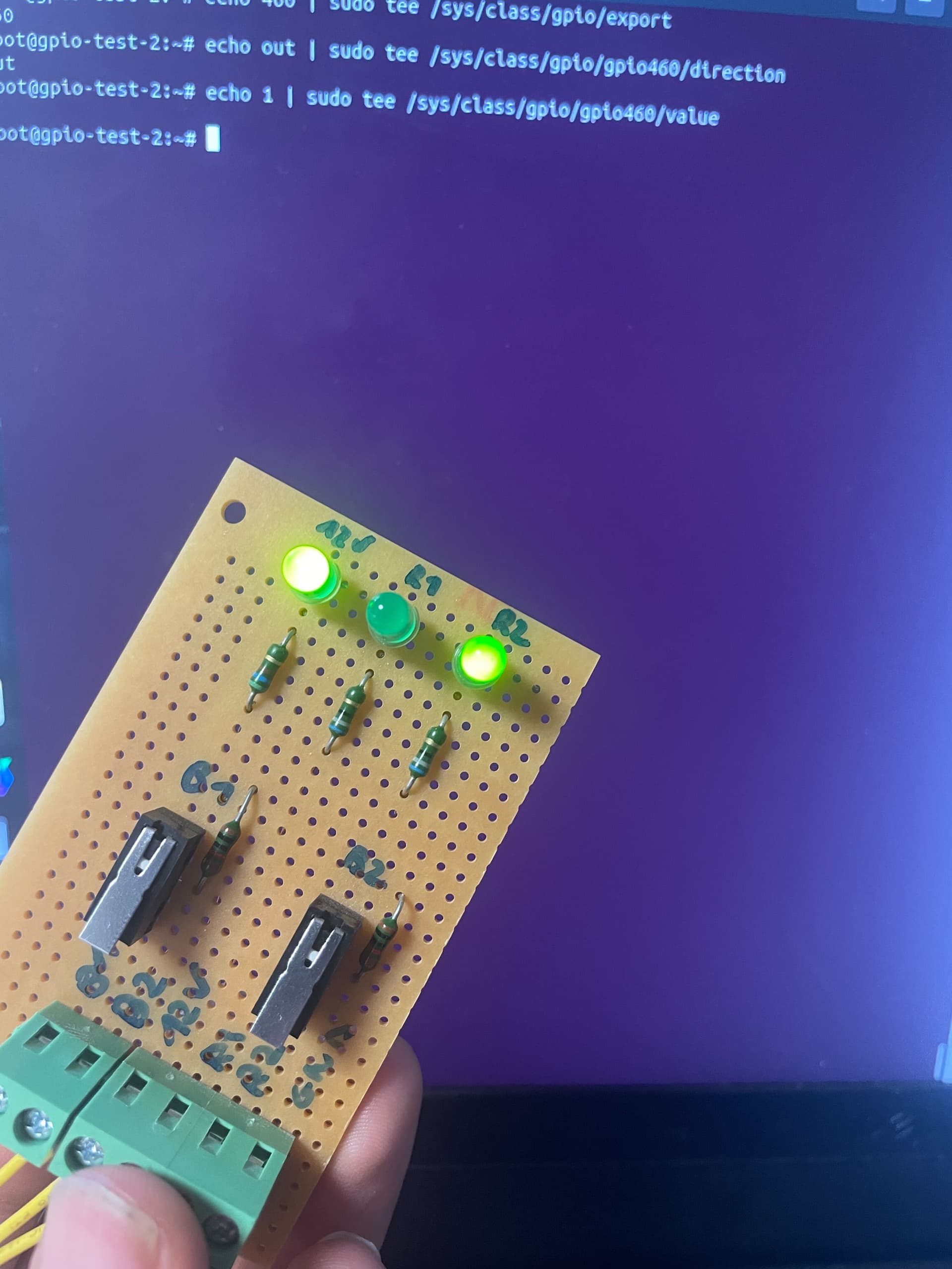
If you compare with the provided documentation, you’ll notice that it’s not the expected behaviour to see the relay get activated when changing the value of the DryContact2 pin: