Has anyone connected one of these boards to display the current playing format information?
According to the author (Ian) all you need to do is supply +5v, GND and the two signals SCK and LRCK/D1 to his board and it uses its onboard analyzer to display the information. I know that it has been done by someone on the following site as part of the review of the KTB: (https://www.audiosciencereview.com/forum/index.php?attachments/img_20190929_140530_2-jpg.34763/) but there were no details. Where can I find the two SCK and LRCK/D1 signals either on the 8 channel Ext connector, the I2S Ext connector or the GPIO header? The signal definitions on the Khadas schematic don’t match the definition used by Ian. Any help would be appreciated!!
1 Like
Ha, yes, I already did that of course! But I don’t see SCK anywhere, so which pin corresponds to SCK?
SCK could mean Slave Clock
LRCK is OK, available, on TB1, D1 too.
Ask Ian if the board is Master Clock driven or Slave driven by TB1.
Then SCK fom Ian’s board would be fed by TB1 MCK (Master Clock).
Those vocabulary concern IIS signal lines definition, it differs from one to others…
Hope this help, correct me gently if not.
Cheers
2 Likes
Many thanks, it makes more sense now since the controller is simply a passive ‘listener’. I will try your suggestion.
HI ABSNimes,
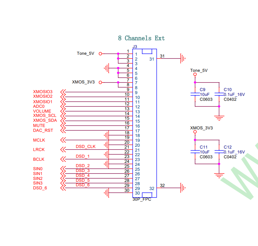
Many thanks for your input. In the end although I discovered a wiring error on my part, I have now got a working system. The connections, all using a 30-pin FPC are:
KTB1 8ch ext. pin 1,2,3 +5v -> ESS controller board +5v
KTB1 8ch ext. pin 4,5,6 GND -> ESS controller board GND
KTB1 8ch ext. pin 21 LRCK -> ESS controller board LRCK input
KTB1 8ch ext. pin 23 BCLK -> ESS controller board SCK input
3 Likes
Hi James,
Glad to see you keep it working as expected 
Nice to share your results, congrats.
Regards
1 Like