Is the eDP output (I-PEX connector, not the Alt-Mode on USB-C) enabled on the Ubuntu Desktop firmware Khadas provides on the Edge Documentation page?
When listing /dev/class/drm the closest match is card0-DP-1, if I’m not mistaken this refers to the Alt-Mode Displayport output on the USB-C connector?
@numbqq Can you help with which files need to be modified to get eDP working on Ubuntu. I used the fenix script and managed to build a working Ubuntu firmware image, but I have no idea which files need to be modified to enable eDP. Can I simply compile a new DTB and replace the existing ones?
Alternatively, is there a firmware image (linux or android) where eDP is already enabled?
Thanks for the response. I do have an eDP panel (LP097QX1), but I’m awaiting the last components to build the backlight driver. I managed to change the DTS file and build a new DTB. (eDP enabled and mapped to VOPB, HDMI switched to VOPL). After replacing the DTB in /boot, I now have a card0-eDP-1 in /sys/class/drm. I also found messages in my kernel log about eDP link training so it seems to be enabled.
I will post my steps here for others once I built the backlight driver and verified that everything is working.
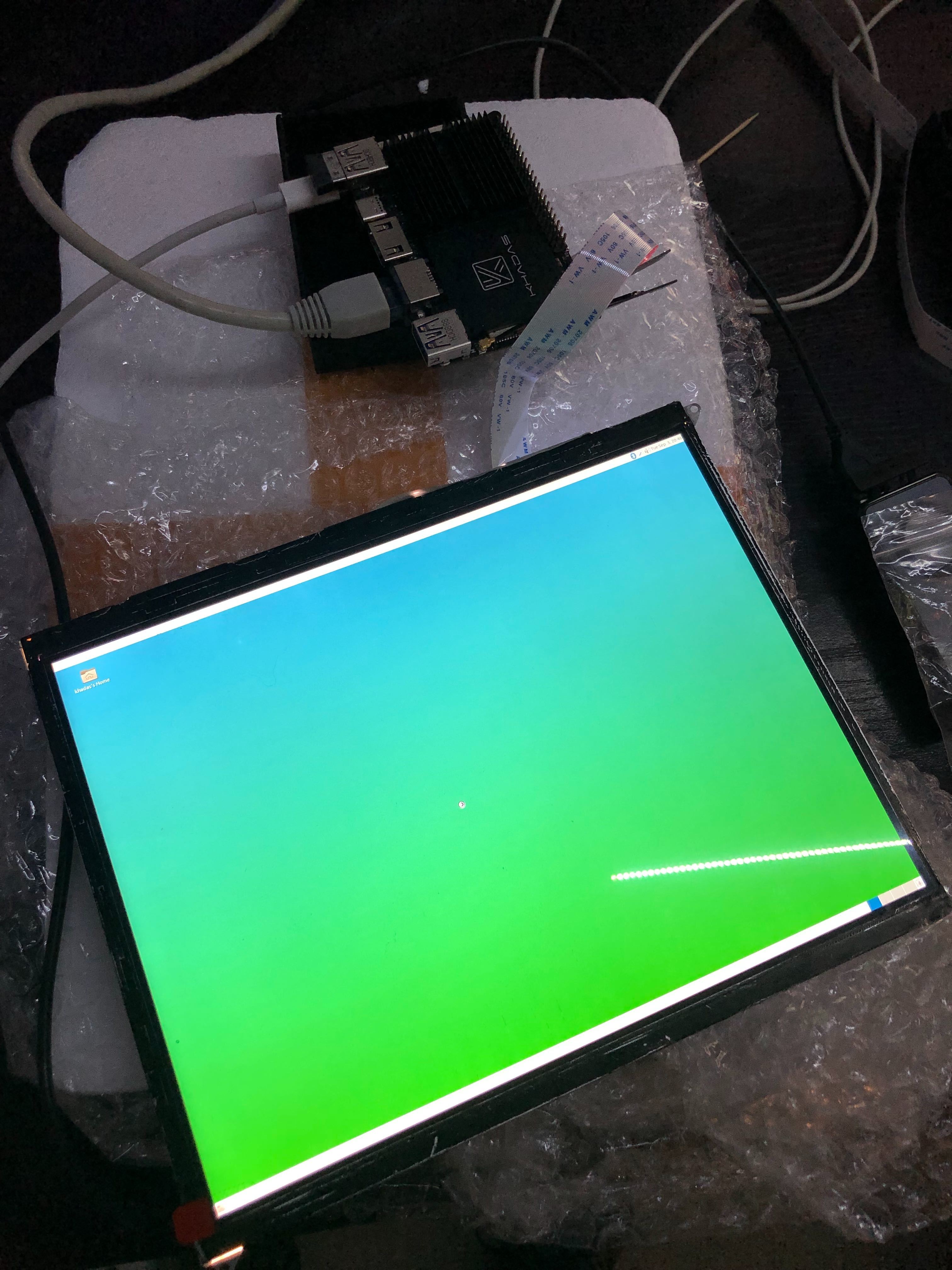
I made some progress with the eDP, although I don’t have anything displaying yet. I have enabled the eDP and mapped VOPB to eDP in the DTB. Here is my DTS file.
[    3.642883] rockchip-dp ff970000.edp: AUX CH command reply failed!
[    3.645771] rockchip-dp ff970000.edp: AUX CH command reply failed!
[    3.645777] rockchip-dp ff970000.edp: LT link start failed!
[    3.645783] rockchip-dp ff970000.edp: eDP link training failed (-110)
When connected the messages change, and DP clock recovery works, but equalization fails
[    4.344905] rockchip-dp ff970000.edp: [drm:analogix_dp_link_start] Enable downspread on the sink
[    4.346560] rockchip-dp ff970000.edp: Link Training Clock Recovery success
[    4.353414] cdn-dp fec00000.dp: Direct firmware load for rockchip/dptx.bin failed with error -2
[    4.354227] rockchip-dp ff970000.edp: EQ Max loop
[    4.355111] rockchip-dp ff970000.edp: LT EQ failed!
[    4.355119] rockchip-dp ff970000.edp: eDP link training failed (-5)
I have verified that the PWM on LCD_BL_PWM (J12 pin 21) is working, VSYS is providing around 12v.
BUT, VCC3V3_S0 (J12 pin 17 and 18) is not providing any power. It measures very close to 0V. Could you please verify if you have the same behaviour. I suppose it is important since the eDP AUXN gets pulled to VCC3V3_S0 according to the schematic, but it appears that the power rail is not turned on.
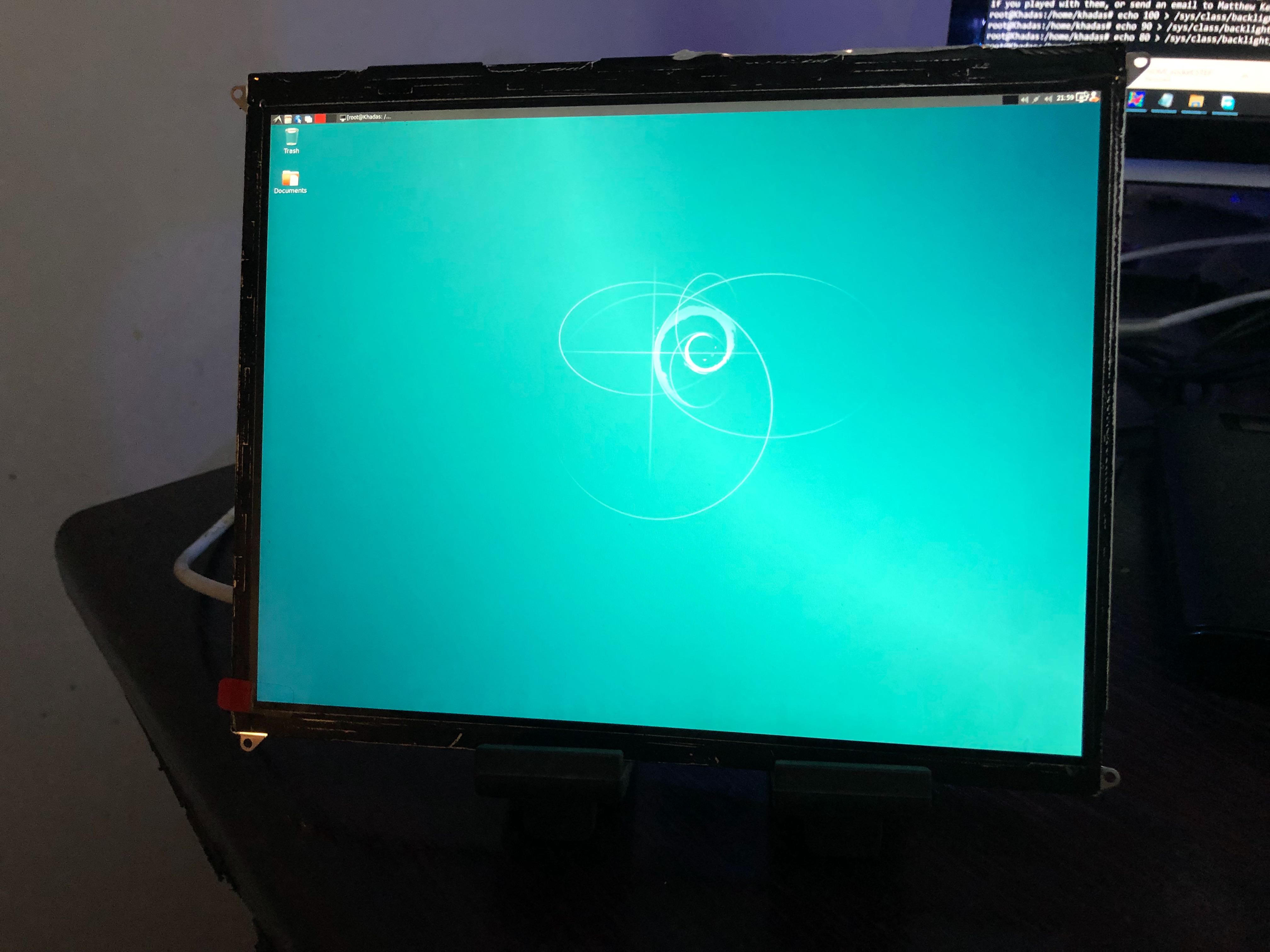
I finally managed to get eDP working on linux. The only change required was to make the appropriate changes to the DTS file, compile it to a DTB and replace it in /boot/dtb.
My DTS file for the panel i’m using is here. The changes I made:
Enable the eDP panel
Configure backlight with PWM mapped to the eDP connector’s BL_PWM pin. Set a default brightness
Enable PWM1 so that backlight dimming works
Configure the eDP node
Route eDP (not sure if this is applicable only to u-boot)
Map HDMI to the low resolution VOP
Map eDP to the high resolution VOP
Some noted for others:
After adding loads more debug logging to the Analogix driver (analogix_dp_core.c), I noticed that after link training fails, the panel requests the Edge to retry with the same voltage and pre-emphasis instead of requesting increased parameters.
My issue was that I was under the impression that the lanes need to be connected in reverse order (i.e. DP_LANE3 to DP_LANE0, DP_LANE2 to DP_LANE1). This was caused by the DisplayPort specification showing the order reversed like this between the source and sink. I was unaware that the cable specification actually performs this swapping as well which means there isn’t really any lane swapping.
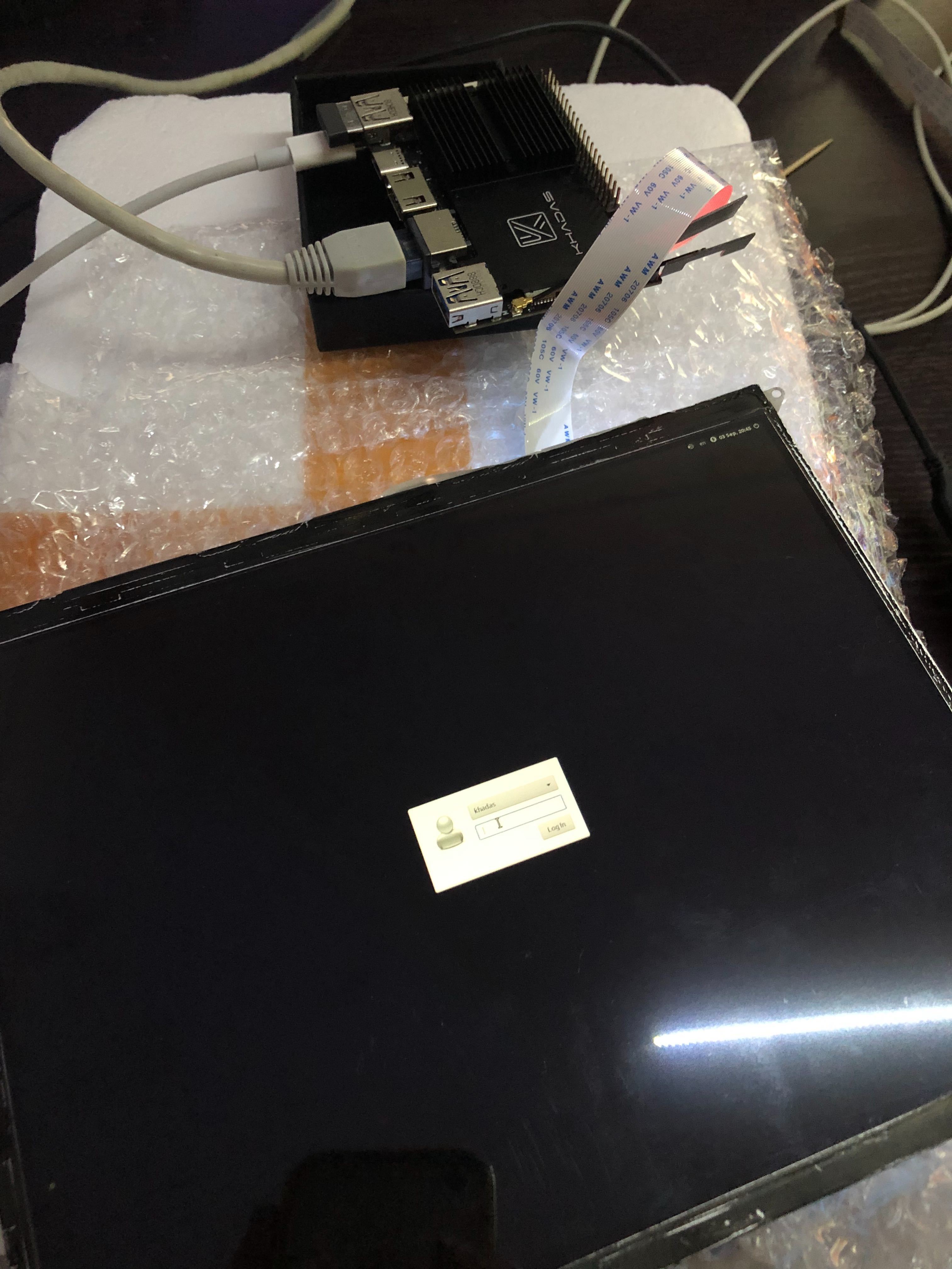
Luckily I had the foresight to place and additional FPC footprint on my controller PCB which allowed me to easily fix the issue. Once the connector was reversed, link training instantly succeeded and the panel lit up with boot messages and a logon screen.
If you see a log messages that clock recovery is OK, but link training failed with error code (-5) then your lanes might be also be reversed, or one lane might be giving trouble.