Brief look at a dual screen portable pc using the Edge2
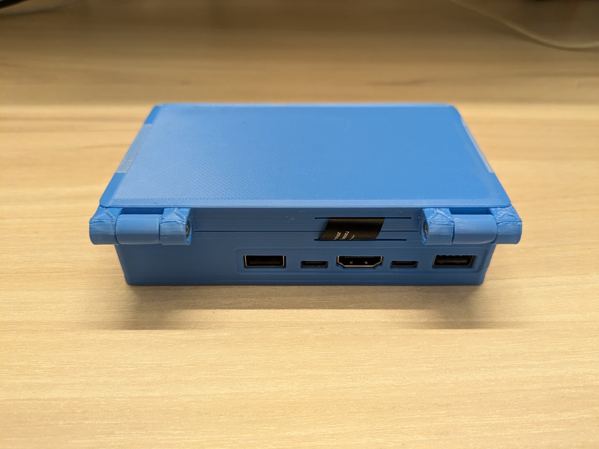
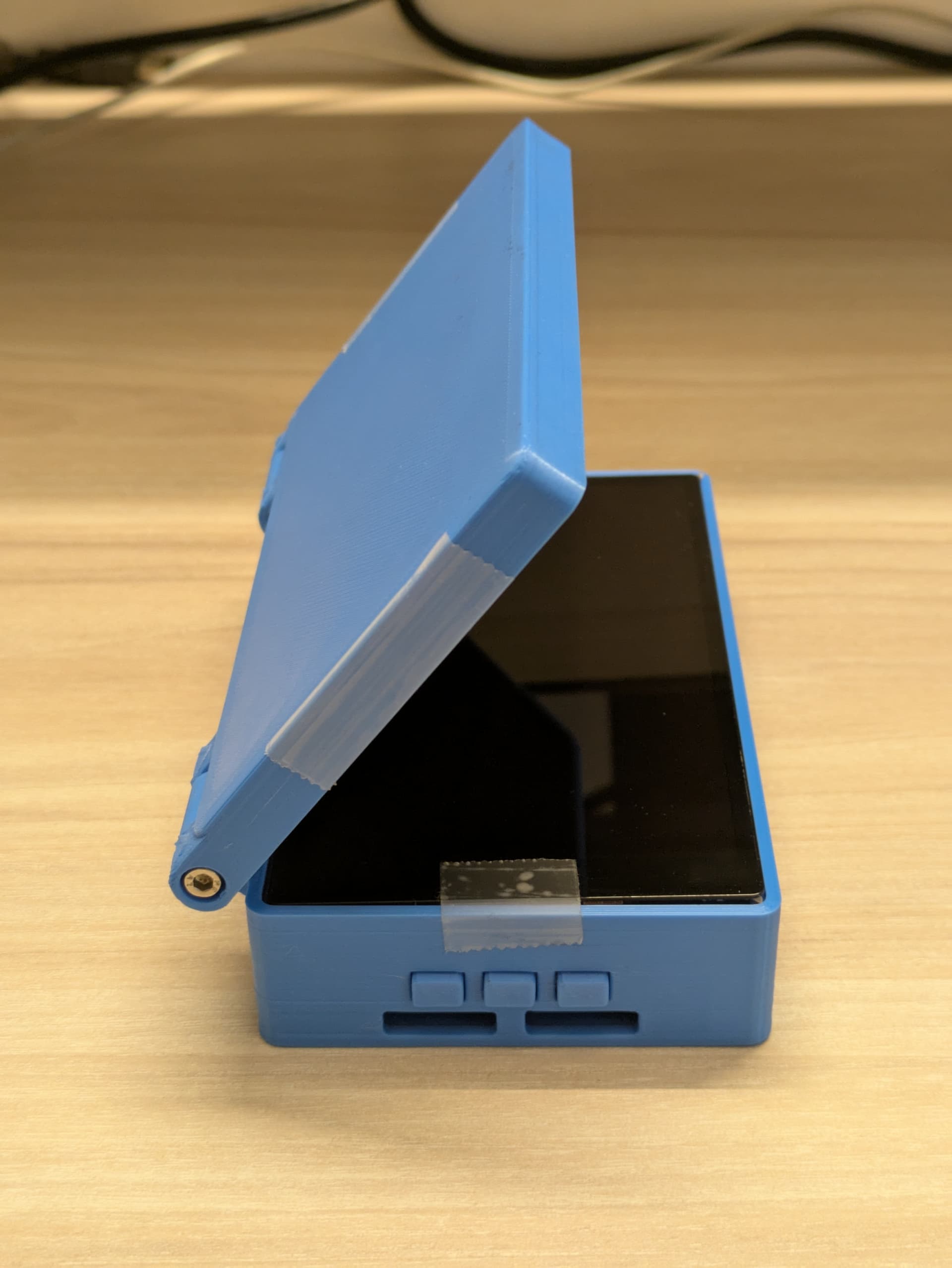

3D printable case design available here: Edge2 dual screen portable pc by sravan senthilnathan | Download free STL model | Printables.com
Instructions on assembly and setup coming soon ![]()
Brief look at a dual screen portable pc using the Edge2
3D printable case design available here: Edge2 dual screen portable pc by sravan senthilnathan | Download free STL model | Printables.com
Instructions on assembly and setup coming soon ![]()
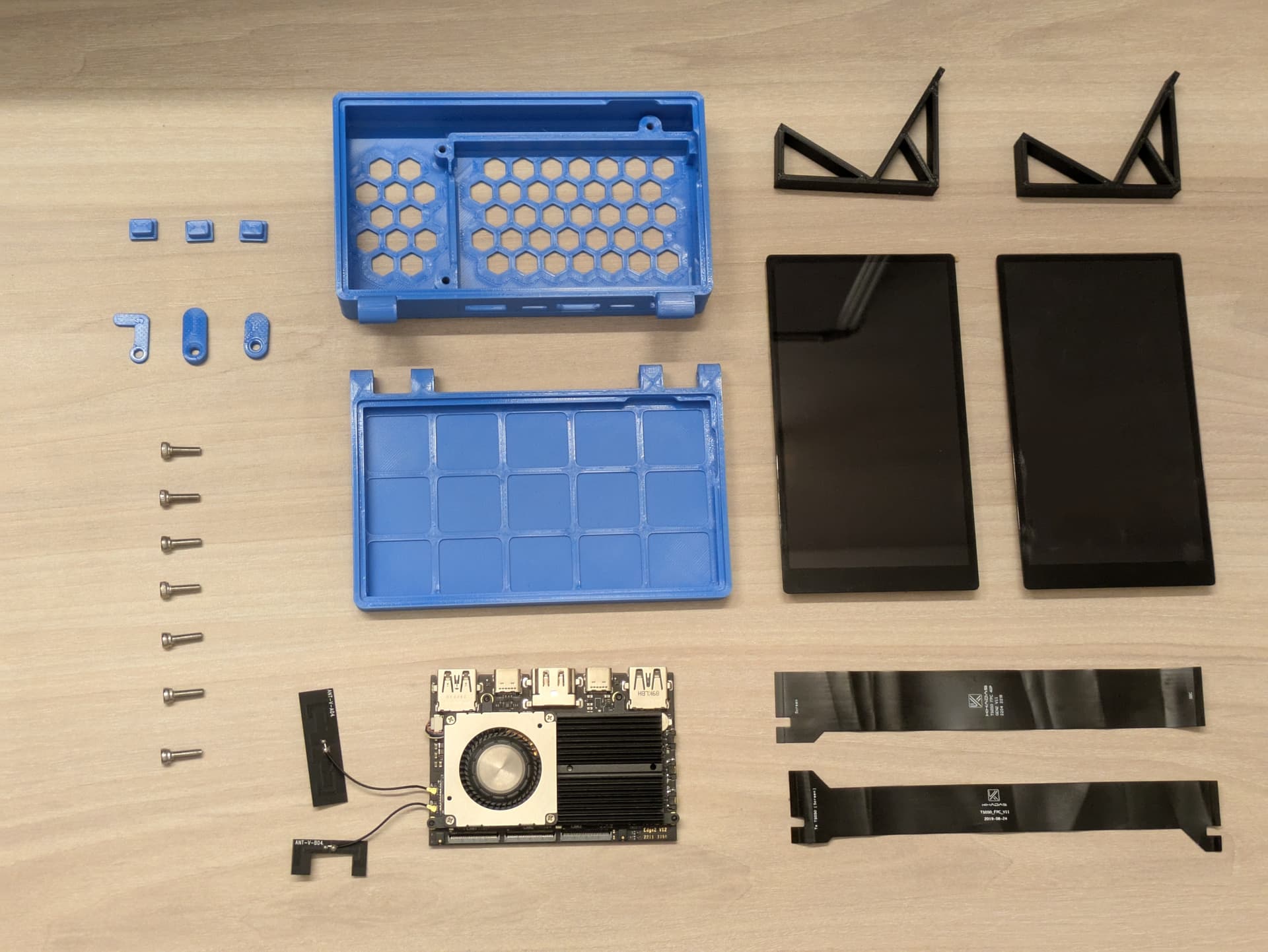
The necessary parts are as follows:
Electronics:
3D printed:
Consumables:
3D printing info:
The models were designed in a way to accept a tolerance level of around ±0.2 mm, printed at 0.16mm layer height.
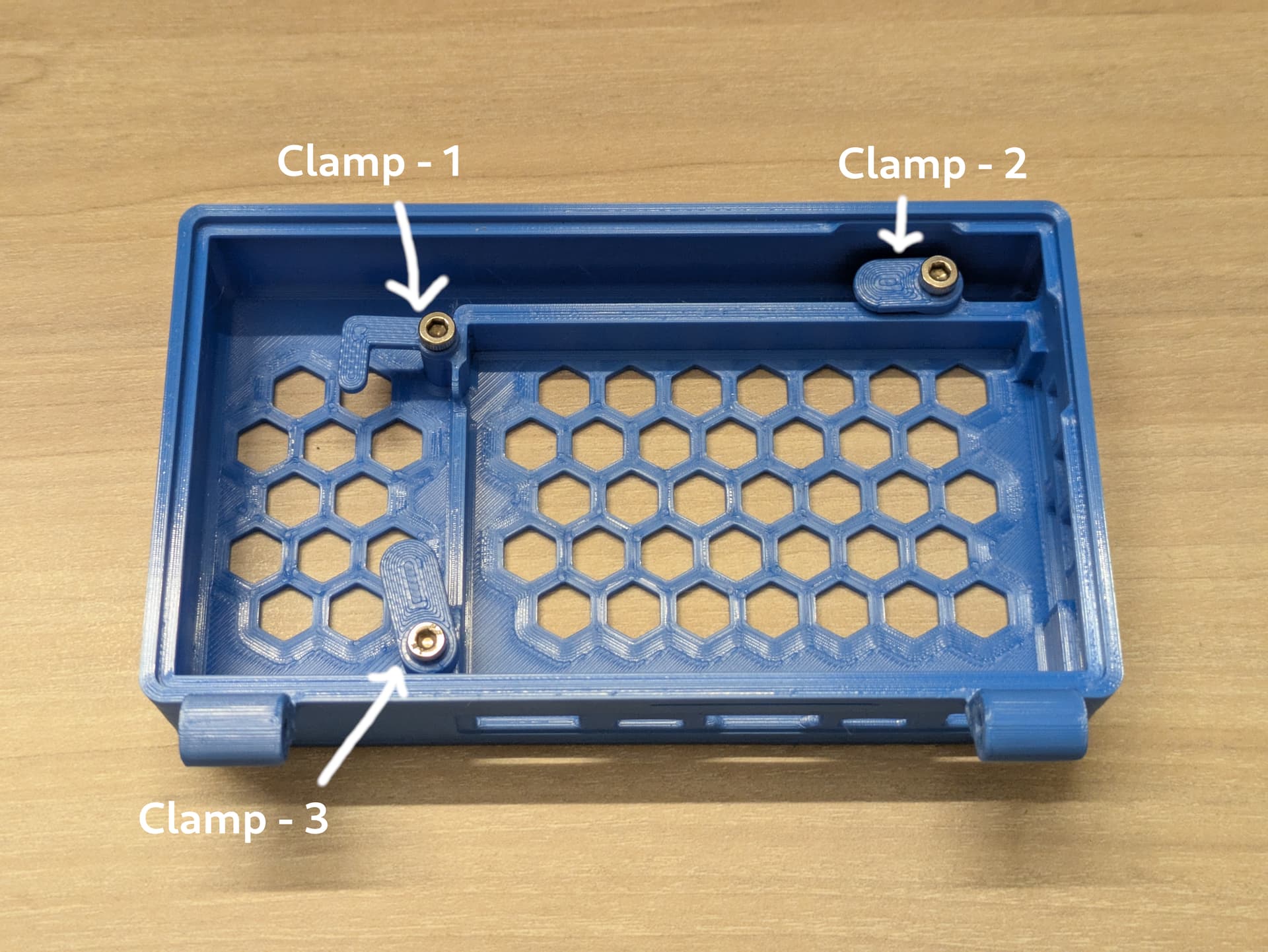
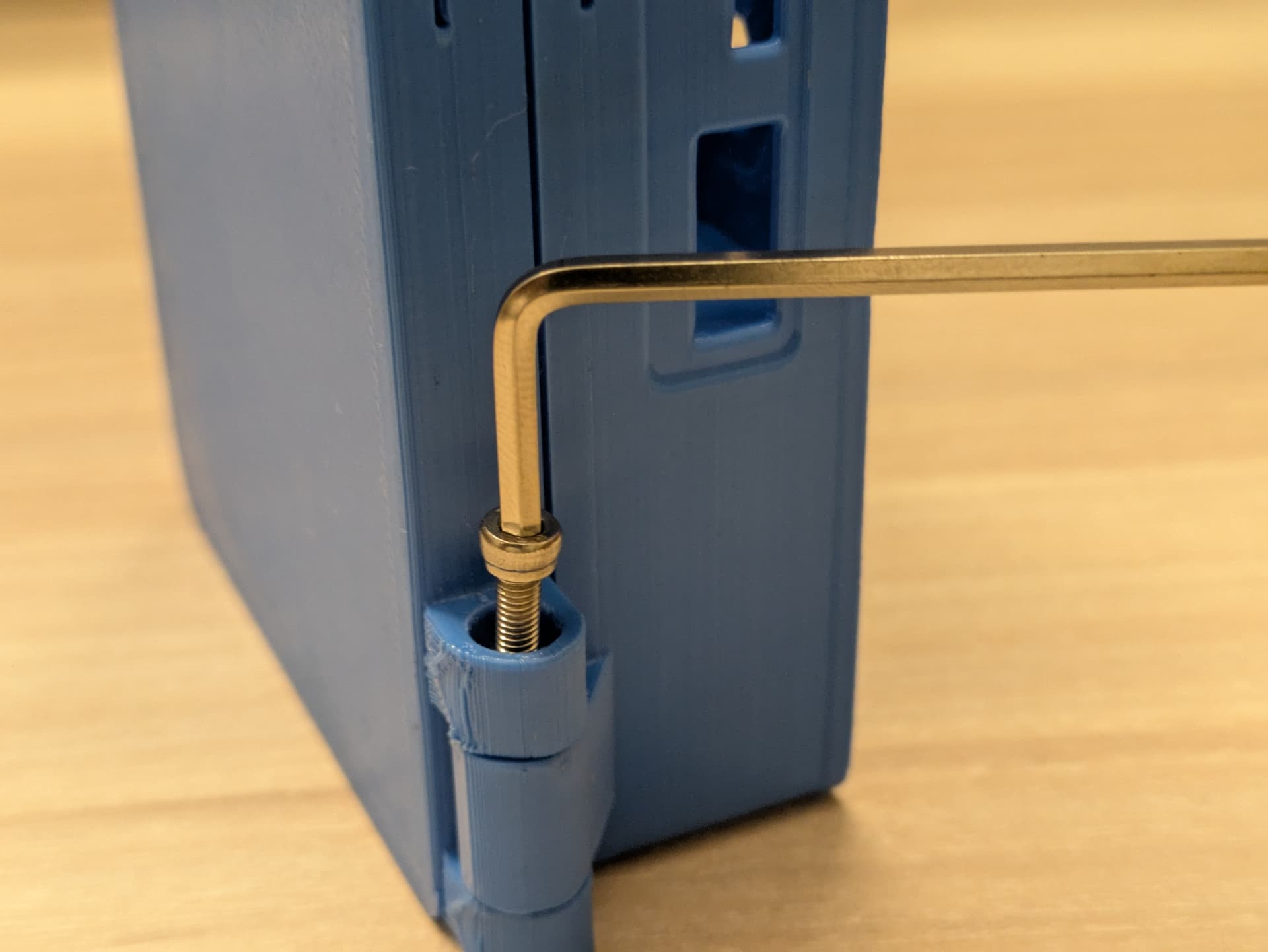
Using the screws, fasten the clamp pieces in the allocated positions.
Once fastened, back the screws by around half a revolution, so the clamp pieces can be swiveled open to allow the board to be placed in the cavity.
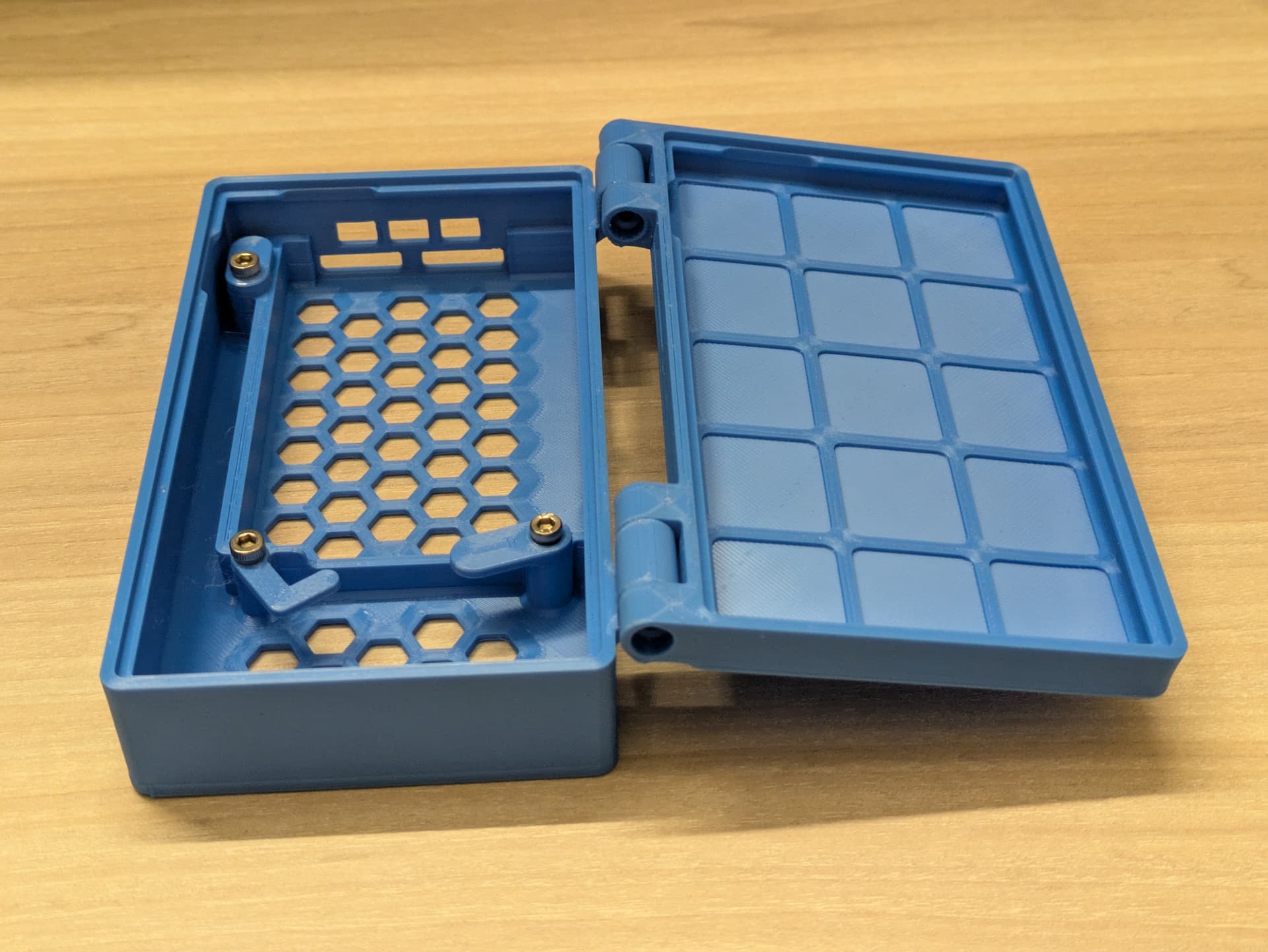
Position the top clamshell so that it somewhat aligns with the hinge portion of the bottom clamshell.
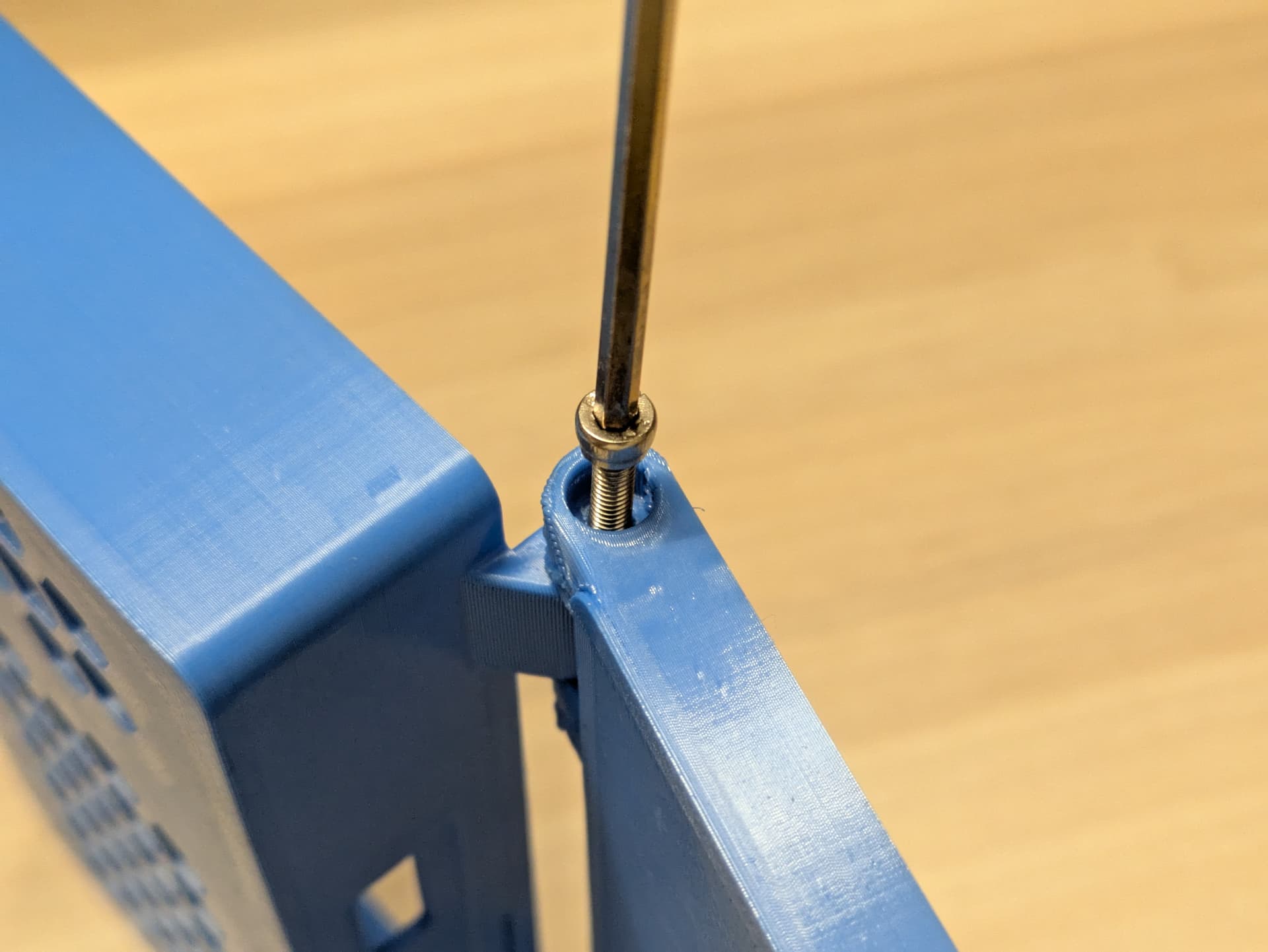
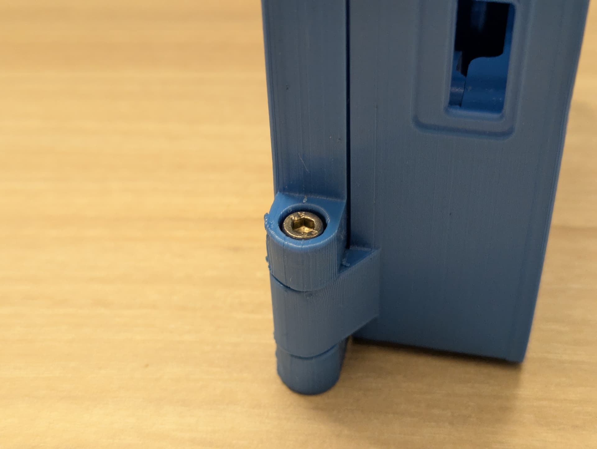
There are two friction hinges, each hinge should require two screws, the outer screws are easier to assemble.
The inner screws may require some patience to assemble.
Ensure the screw head is flush, and tighten until force is required, it may need some tuning, but when assembled the hinge should have enough friction to hold the top clamshell in any angle from 0, up to 225 degrees.
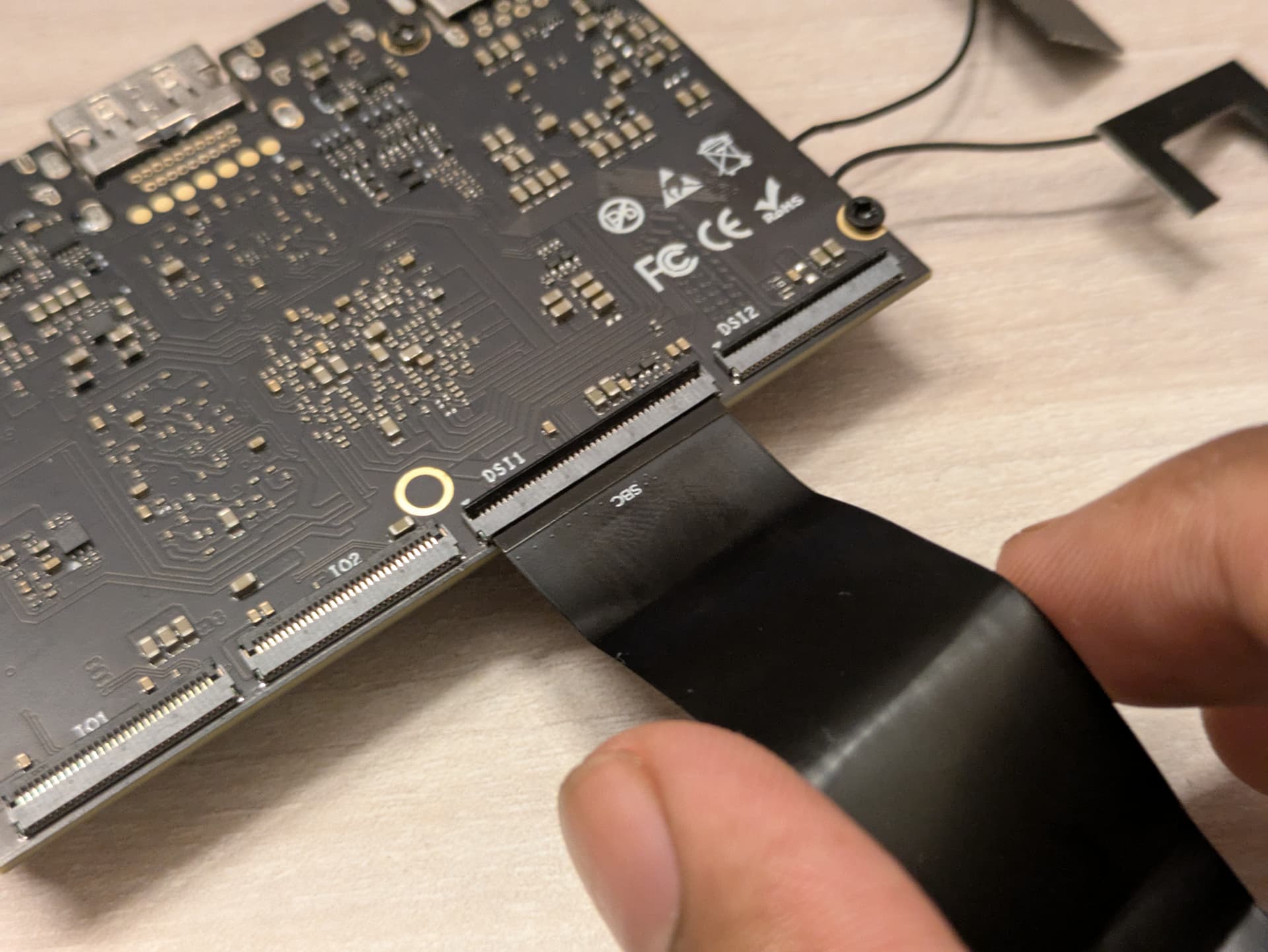
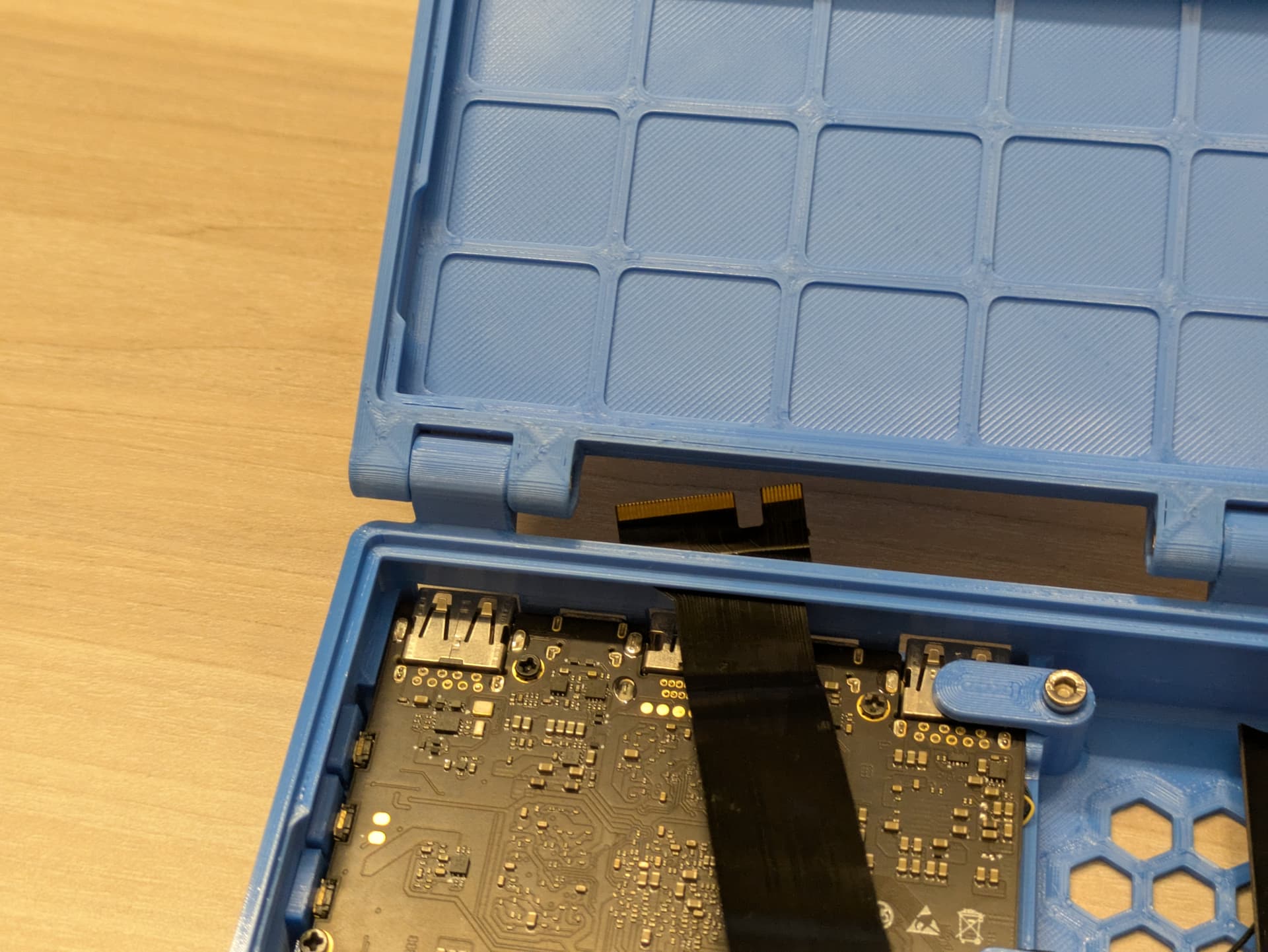
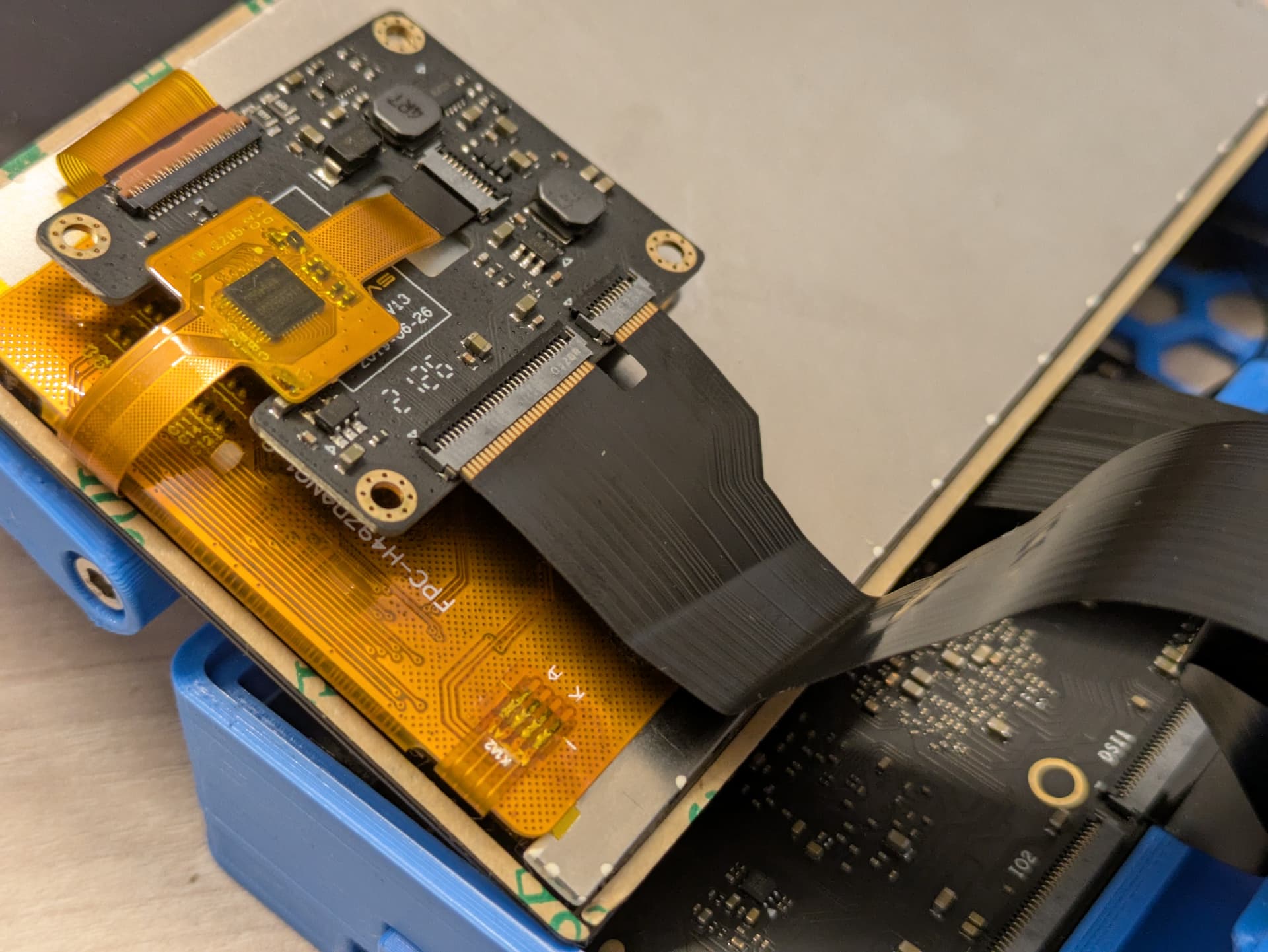
Attach just the FPC cables for now on the Edge2.
You will note that the 10-pin portion of the old FPC cable is left floating, this means the upper panel will not have any touch functionality, only the lower panel will. You can apply a strip of some polyamide tape to insulate it.
Set aside the board, and assemble the buttons on the case, they should drop into place, they do not have any retaining mechanism, so you may need to be cautious as they can fall out of place.
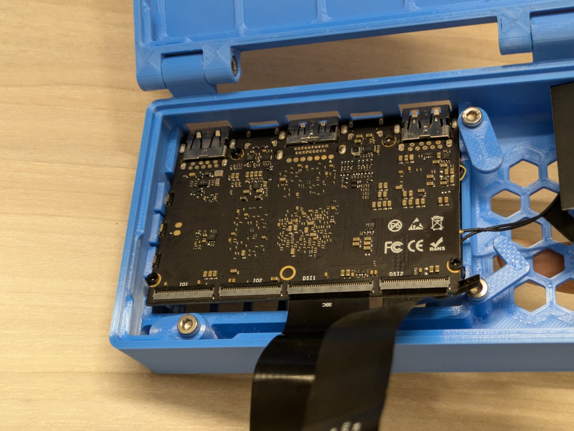
After placing the buttons in their place, drop the Edge2 into the cavity.
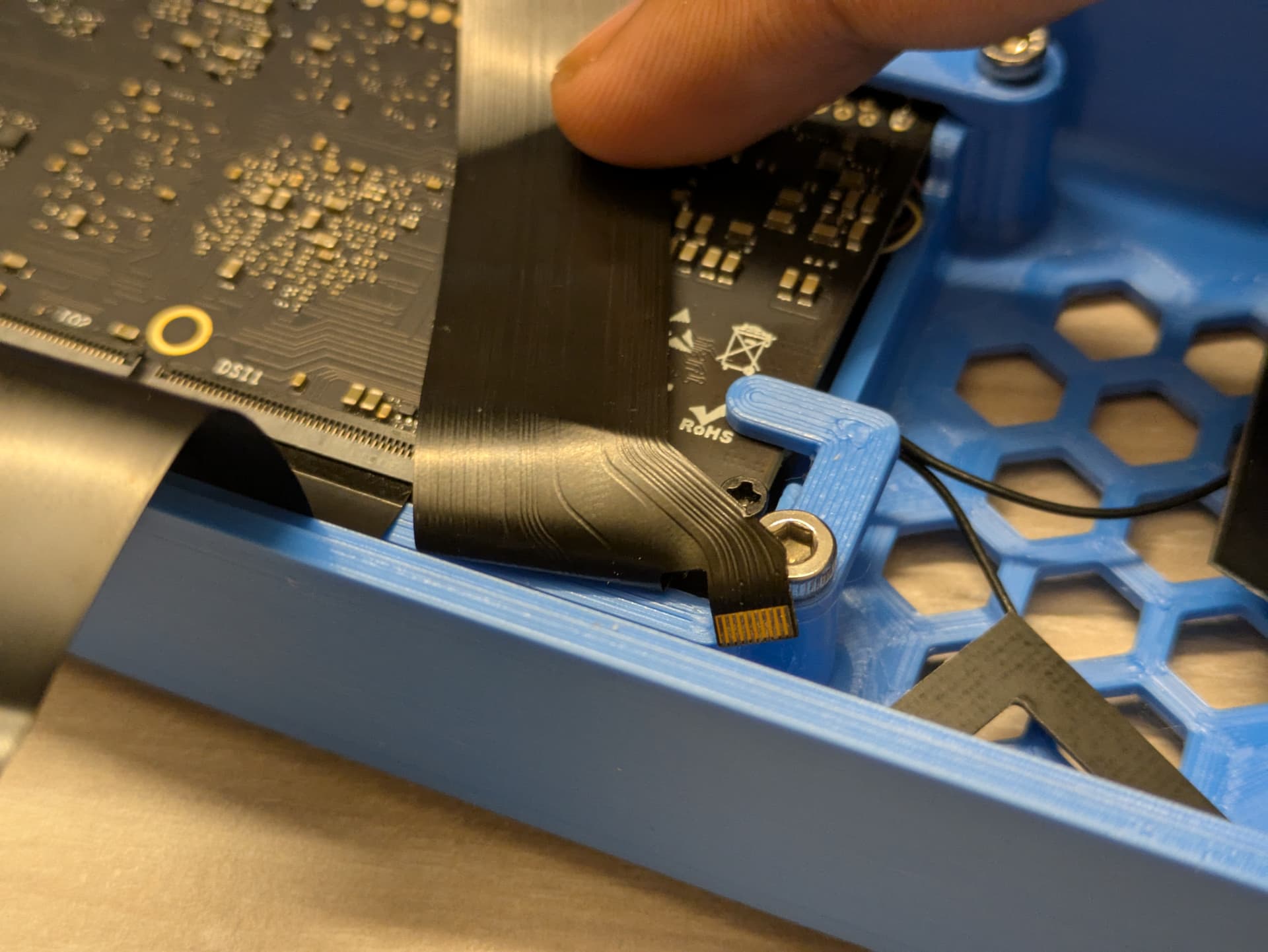
Close all the clamps, and tighten the screws as necessary, and feed the FPC cable to the top portion through the dedicated cutouts.
After which, fold the 10-pin portion.
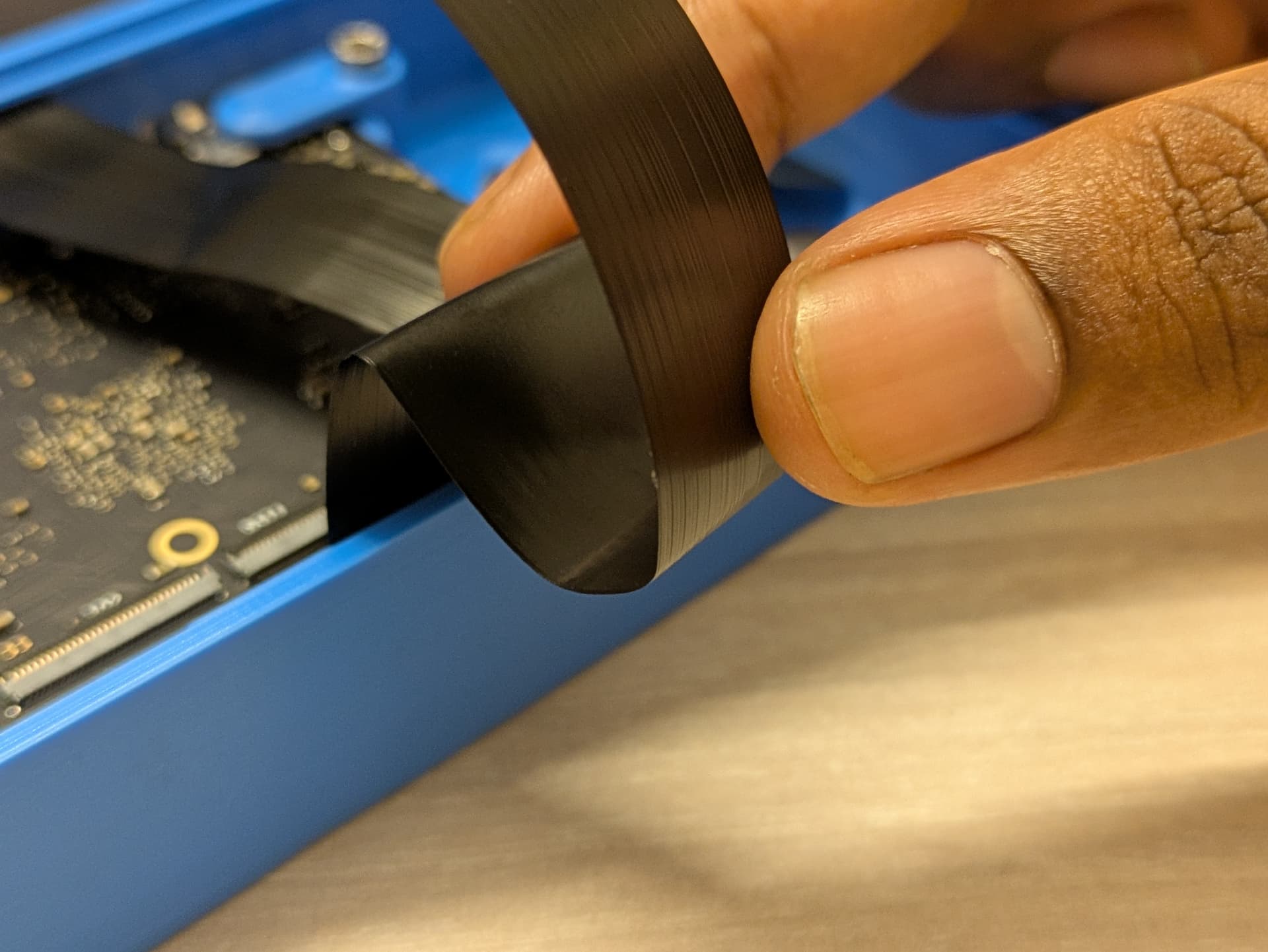
Fold the 40-pin FPC cable as follows to fit it inside the case.
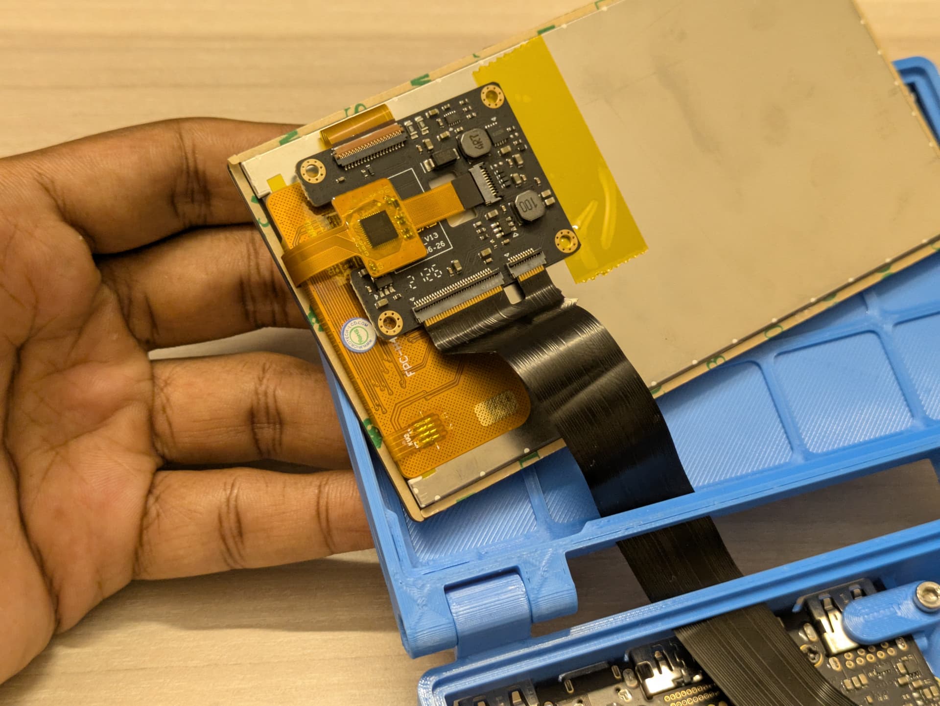
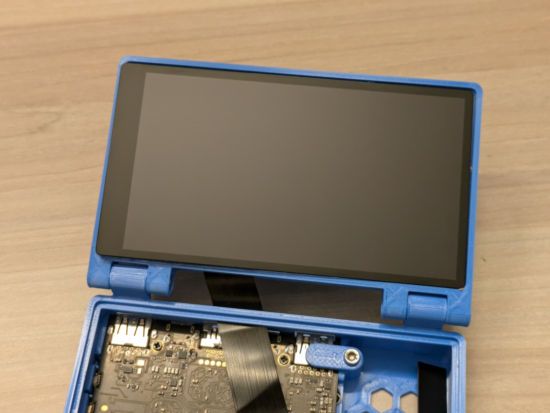
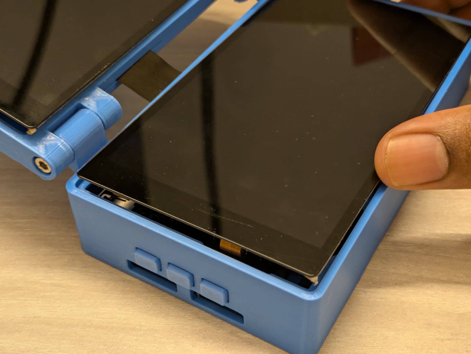
Attach the top panel with the FPC cable
Once attached, flip the panel, so that it can sit in the clamshell, the FPC cable should have some slack in it, so that there is no tension exerted on the connectors of the LCD board or the Edge2, which can otherwise damage it.
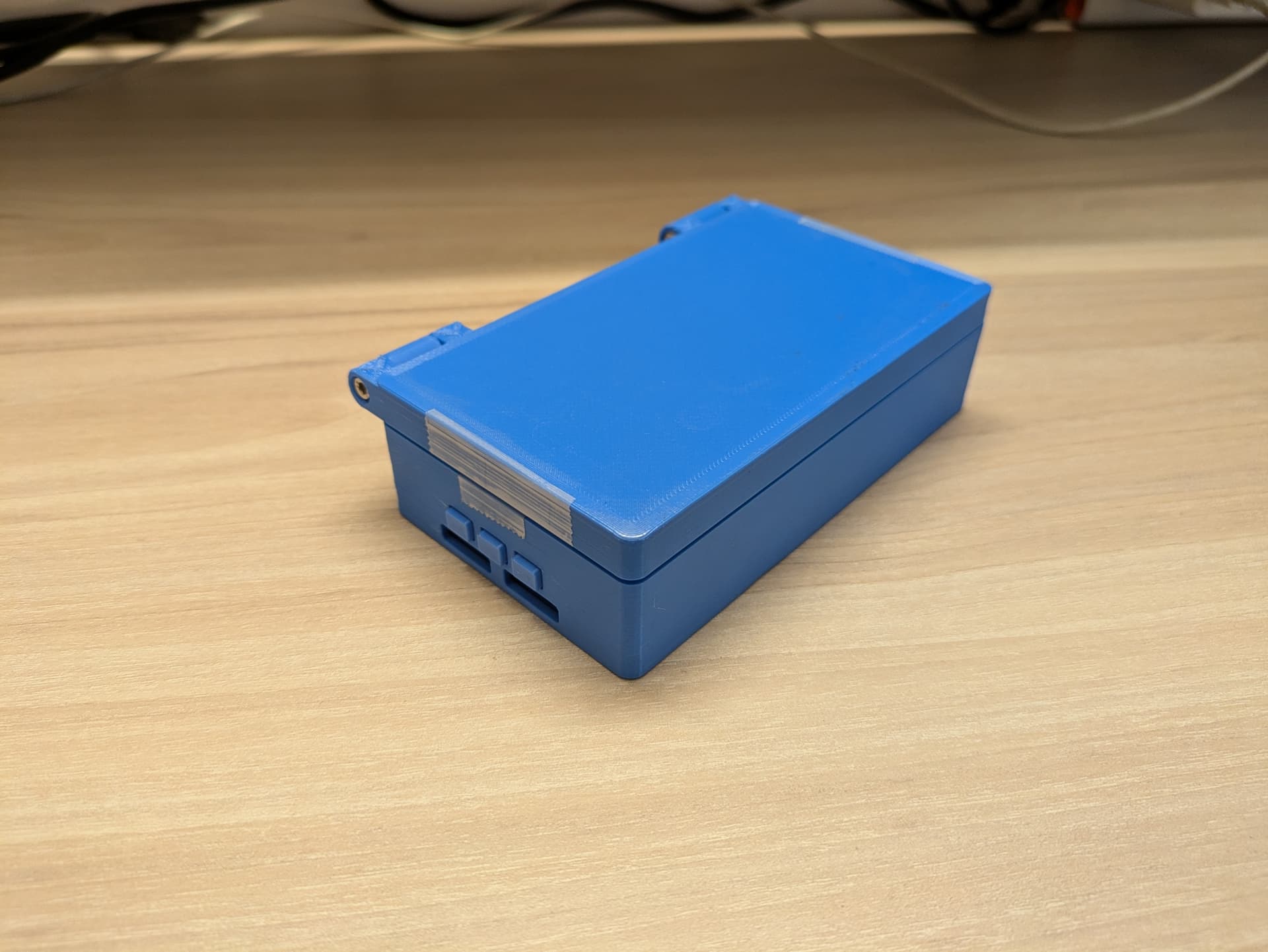
When completed correctly, it should look like this
You can remove the adhesive strips along the edges of the panels and affix them to make the assembly permanent.
The software setup provided is for the Fenix images with the 6.1 kernel.
Configure Fenix according to the docs on a suitable host computer, Refer to: GitHub - khadas/fenix: One-stop script set to build Ubuntu/Debian images
Configure the environment with the following variables, using the setenv.sh script.
KHADAS_BOARD=Edge2
LINUX=6.1
UBOOT=2017.09
DISTRIBUTION=Ubuntu
DISTRIB_RELEASE=noble
DISTRIB_TYPE=gnome
DISTRIB_ARCH=arm64
INSTALL_TYPE=EMMC
make kernel-deb to set up the necessary dependencies, toolchains and kernel sources.$ cd build/linux
mod.patch file using a text editor and running git apply mod.patch, or manually applying the changes:diff --git a/arch/arm64/boot/dts/rockchip/rk3588s-khadas-edge2.dts b/arch/arm64/boot/dts/rockchip/rk3588s-khadas-edge2.dts
index c398241e3d60..0428480a5a62 100644
--- a/arch/arm64/boot/dts/rockchip/rk3588s-khadas-edge2.dts
+++ b/arch/arm64/boot/dts/rockchip/rk3588s-khadas-edge2.dts
@@ -246,7 +246,7 @@ &backlight_mipi0 {
&backlight_mipi1 {
pwms = <&pwm13 0 25000 0>;
power-supply = <&vcc3v3_lcd2_en>;
- status = "disabled";
+ status = "okay";
};
@@ -255,11 +255,11 @@ &combphy0_ps {
};
&dp0 {
- status = "okay";
+ status = "disabled";
};
&dp0_in_vp2 {
- status = "okay";
+ status = "disabled";
};
&dp0_sound{
@@ -267,7 +267,7 @@ &dp0_sound{
};
&dsi0 {
- status = "disabled";
+ status = "okay";
reset-delay-ms = <20>;
reset-gpios = <&gpio4 RK_PA3 GPIO_ACTIVE_HIGH>;
pinctrl-names = "default";
@@ -281,11 +281,11 @@ &dsi0_panel {
};
&dsi0_in_vp2 {
- status = "disabled";
+ status = "okay";
};
&dsi0_in_vp3 {
- status = "okay";
+ status = "disabled";
};
&hdmi0_sound {
@@ -294,7 +294,7 @@ &hdmi0_sound {
&route_dsi0 {
status = "okay";
- connect = <&vp3_out_dsi0>;
+ connect = <&vp2_out_dsi0>;
};
&mipi_dcphy0 {
@@ -306,11 +306,11 @@ &dsi1 {
reset-gpios = <&gpio4 RK_PA7 GPIO_ACTIVE_HIGH>;
pinctrl-names = "default";
pinctrl-0 = <&lcd2_rst_gpio1>;
- status = "disabled";
+ status = "okay";
};
&dsi1_panel {
- status = "disabled";
+ status = "okay";
power-supply = <&vcc3v3_lcd2_en>;
};
@@ -323,11 +323,11 @@ &dsi1_in_vp2 {
};
&dsi1_in_vp3 {
- status = "disabled";
+ status = "okay";
};
&route_dsi1 {
- status = "disabled";
+ status = "okay";
connect = <&vp3_out_dsi1>;
};
diff --git a/arch/arm64/boot/dts/rockchip/rk3588s-khadas-edge2.dtsi b/arch/arm64/boot/dts/rockchip/rk3588s-khadas-edge2.dtsi
index 2c1f0d818e3d..b684364b6dc1 100644
--- a/arch/arm64/boot/dts/rockchip/rk3588s-khadas-edge2.dtsi
+++ b/arch/arm64/boot/dts/rockchip/rk3588s-khadas-edge2.dtsi
@@ -285,7 +285,7 @@ &cpu_b2 {
};
&dsi0 {
- status = "disabled";
+ status = "okay";
//rockchip,lane-rate = <1000>;
dsi0_panel: panel@0 {
status = "okay";
@@ -924,10 +924,10 @@ dsi_out_panel: endpoint {
};
&dsi1 {
- status = "disabled";
+ status = "okay";
//rockchip,lane-rate = <1000>;
dsi1_panel: panel@0 {
- status = "disabled";
+ status = "okay";
compatible = "simple-panel-dsi";
reg = <0>;
backlight = <&backlight_mipi1>;
$ cd ../../
$ make
The image that is generated in build/images can be flashed to your board, you can follow the documentation to understand that procedure:
Edge2 Install OS into eMMC via USB Flash Tool [Khadas Docs]
Alternative: If you already have Ubuntu set up on your device, you can use the kernel and device tree packages generated in build/images/debs/$VERSION/Edge2/, eg.
zephyr@vertex:~/workspace/fenix/build/images/debs/1.7.3/Edge2$ ls *.deb
linux-dtb-rockchip-6.1_1.7.3_arm64.deb  linux-headers-rockchip-6.1_1.7.3_arm64.deb  linux-image-rockchip-6.1_1.7.3_arm64.deb  linux-u-boot-edge2-vendor_1.7.3-2017.09_arm64.deb
Copy these package files to your board and install them using dpkg.
Brightness Control Fix
The GNOME desktop only provides controls for the brightness control of one single display panel, we can create a simple systemd service that can monitor and change the display brightness of the second panel based on the primary panel brightness:
$ sudo nano /etc/systemd/system/dual-dsi-brightness.service
[Unit]
Description=Brightness control for dual dsi display
After=network.target

[Service]
User=root
Type=simple
ExecStart=/bin/bash -c "while true; do cat /sys/class/backlight/backlight-mipi0/brightness > /sys/class/backlight/backlight-mipi1/brightness; sleep 0.1; done"
Restart=always

[Install]
WantedBy=multi-user.target
$ systemctl daemon-reload
$ systemctl enable dual-dsi-brightness.service
$ systemctl start dual-dsi-brightness.service
Cool~ Thank you for sharing, Sravan. ![]()