1. Brief Introduction
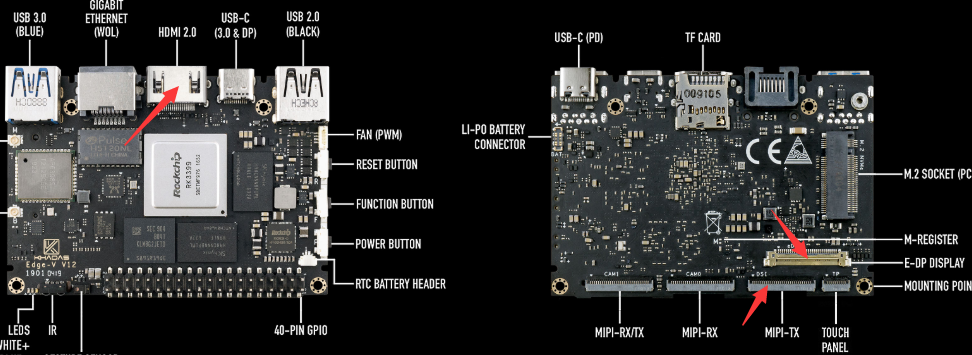
Edge-V has three display interfaces: HDMI + MIPI + EDP. The position of the interfaces are shown below:
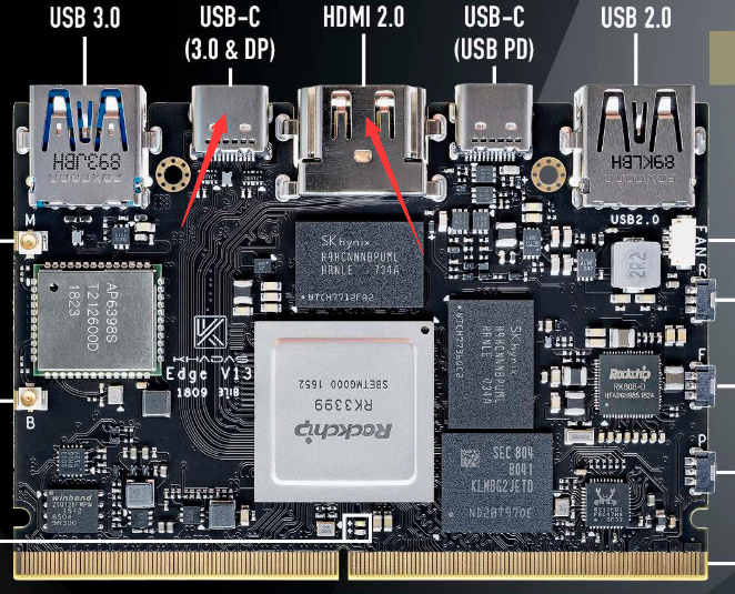
Edge has two LCD screen interfaces: HDMI + DP. The position of the interfaces are shown below:
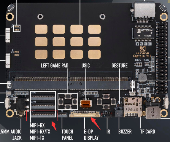
Captain has two LCD screen interfaces: EDP + MIPI. The position of the interfaces are shown below:
2. (HDMI + DP) Screen Config
2.1 Configure DTS
rk3399-khadas-edge.dtsi, for example: HDMI (Main Display) + DP (Secondary Display)
2.1.1 Enable Corresponding Display Device Nodes
&hdmi {
	status = "okay";
	rockchip,phy-table =
		<74250000 0x8009 0x0004 0x0272>,
		<165000000 0x802b 0x0004 0x0209>,
		<297000000 0x8029 0x0005 0x028d>,
		<594000000 0x8039 0x0000 0x0090>,
		<000000000 0x0000 0x0000 0x0000>;
};

&cdn_dp {
	status = "okay";
	extcon = <&fusb0>;
	phys = <&tcphy0_dp>;
};
2.1.2 Bind VOP
The RK3399 platform has two VOPs: vopb (Supports 4K), and vopl (Supports 2K). When the display device node opens, the ports corresponding to vopb and vopl will be opened, and the unused VOP will need to be turned off.
&hdmi_in_vopb {
	status = "okay";
};

&hdmi_in_vopl {
	status = "disabled";
};

&dp_in_vopb {
	status = "disabled";
};

&dp_in_vopl {
	status = "okay";
};
2.1.3 Boot Logo
If the uboot logo is not turned on, the kernel boot-stage cannot display the boot logo, and it can only be seen after Android boots. In dts, it is possible to turn on uboot logo support by setting the corresponding routes; such as enabling the uboot logo to be displayed via HDMI:
&route_hdmi {
	status = "okay";
	connect = <&vopb_out_hdmi>;
};
2.1.4 Binding PLL
The VOP clock bound by the HDMI of rk3399 needs to be mounted on the vpll. If the dual display requires another VOP clock on the cpll, the frequency of any DCLK can be distinguished.
For example, when HDMI is bound to vopb:
&vopb {
	assigned-clocks = <&cru DCLK_VOP0_DIV>;
	assigned-clock-parents = <&cru PLL_VPLL>;
};
&vopl {
	assigned-clocks = <&cru DCLK_VOP1_DIV>;
	assigned-clock-parents = <&cru PLL_CPLL>;
};
And when HDMI is bound to vopl:
&vopb {
	assigned-clocks = <&cru DCLK_VOP0_DIV>;
	assigned-clock-parents = <&cru PLL_CPLL>;
};
&vopl {
	assigned-clocks = <&cru DCLK_VOP1_DIV>;
	assigned-clock-parents = <&cru PLL_VPLL>;
};
2.1.5 Turn On Audio Output
&dp_sound {
	status = "okay";
};

&hdmi_sound {
	status = "okay";
};
2.2 Main and Secondary Display Config
android 9.0 Config
device/rockchip/rk3399/rk3399.mk
PRODUCT_PROPERTY_OVERRIDES += \
    vendor.hwc.device.primary=HDMI-A \
    vendor.hwc.device.extend=DP
	#vendor.hwc.device.extend=DSI
    #vendor.hwc.device.extend=eDP
android 7.1 Config
device/rockchip/rk3399/rk3399_all.mk
PRODUCT_PROPERTY_OVERRIDES += \
    sys.hwc.device.primary=HDMI-A \
    sys.hwc.device.extend=DP
	#sys.hwc.device.extend=DSI
    #sys.hwc.device.extend=eDP
3. (MIPI + HDMI) Screen Config
3.1 Configuring DTS
rk3399-khadas-edge-mipi-android.dtsi, for example: MIPI (Main Display) + HDMI (Secondary Display).
3.1.1 Enable Corresponding Display Device Nodes
&hdmi {
	status = "okay";
	rockchip,phy-table =
		<74250000 0x8009 0x0004 0x0272>,
		<165000000 0x802b 0x0004 0x0209>,
		<297000000 0x8029 0x0005 0x028d>,
		<594000000 0x8039 0x0000 0x0090>,
		<000000000 0x0000 0x0000 0x0000>;
};

&cdn_dp {
	status = "disabled";
};

&dsi {
    status = "okay";
};
3.1.2 Binding VOP
RK3399 platform has two VOP: vopb (Supports 4K) and vopl (Supports 2K). When the display device node opens, the ports corresponding to vopb and vopl will be opened, and the unused VOP will need to be turned off.
&dp_in_vopl {
	status = "disabled";
};

&dp_in_vopb {
	status = "disabled";
};

&hdmi_in_vopl {
	status = "okay";
};

&hdmi_in_vopb {
	status = "disabled";
};

&dsi_in_vopl {
	status = "disabled";
};

&dsi_in_vopb {
	status = "okay";
};
3.1.3 Boot Logo
If the uboot logo is not turned on, the kernel booting stage cannot display the boot logo, and it can only be seen after Android boots. In dts, it is possible to turn on uboot logo support by setting the corresponding routes, such as enabling the uboot logo to be displayed via HDMI:
&route_hdmi {
	status = "okay";
	connect = <&vopl_out_hdmi>;
};

&route_dsi {
	status = "okay";
	connect = <&vopb_out_dsi>;
};
3.1.4 Binding PLL
The VOP clock bound by the HDMI of rk3399 needs to be mounted on the vpll. If the dual display requires another VOP clock on the cpll, the frequency of any DCLK can be distinguished.
For example, when HDMI is bound to vopb:
&vopb {
	assigned-clocks = <&cru DCLK_VOP0_DIV>;
	assigned-clock-parents = <&cru PLL_VPLL>;
};
&vopl {
	assigned-clocks = <&cru DCLK_VOP1_DIV>;
	assigned-clock-parents = <&cru PLL_CPLL>;
};
Configure when HDMI is bound to vopl:
&vopb {
	assigned-clocks = <&cru DCLK_VOP0_DIV>;
	assigned-clock-parents = <&cru PLL_CPLL>;
};
&vopl {
	assigned-clocks = <&cru DCLK_VOP1_DIV>;
	assigned-clock-parents = <&cru PLL_VPLL>;
};
3.1.5 Turn On Audio Output
&dp_sound {
	status = "disabled";
};

&hdmi_sound {
	status = "okay";
};
3.1.6 Configure Timing
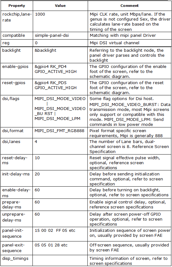
&dsi {
status = "okay";
rockchip,lane-rate = <1000>;
dsi_panel: panel@0 {
status = "okay";
compatible = "simple-panel-dsi";
reg = <0>;
backlight = <&backlight>;
reset-gpios = <&gpio4 RK_PD4 GPIO_ACTIVE_HIGH>; /* GPIO4_D4 */
enable-gpios = <&gpio4 RK_PD5 GPIO_ACTIVE_HIGH>; /* GPIO4_D5 */
// pinctrl-names = "default";
// pinctrl-0 = <&lcd_reset_gpio>, <&lcd_enable_gpio>;
reset-delay-ms = <10>;
enable-delay-ms = <60>;
prepare-delay-ms = <60>;
unprepare-delay-ms = <60>;
disable-delay-ms = <60>;
dsi,flags = <(MIPI_DSI_MODE_VIDEO | MIPI_DSI_MODE_VIDEO_BURST |
MIPI_DSI_MODE_LPM | MIPI_DSI_MODE_EOT_PACKET)>;
dsi,format = <MIPI_DSI_FMT_RGB888>;
dsi,lanes = <4>;
panel-init-sequence = [
15 00 02 FF 05
....
05 0A 01 29
];
panel-exit-sequence = [
05 05 01 28
05 78 01 10
];
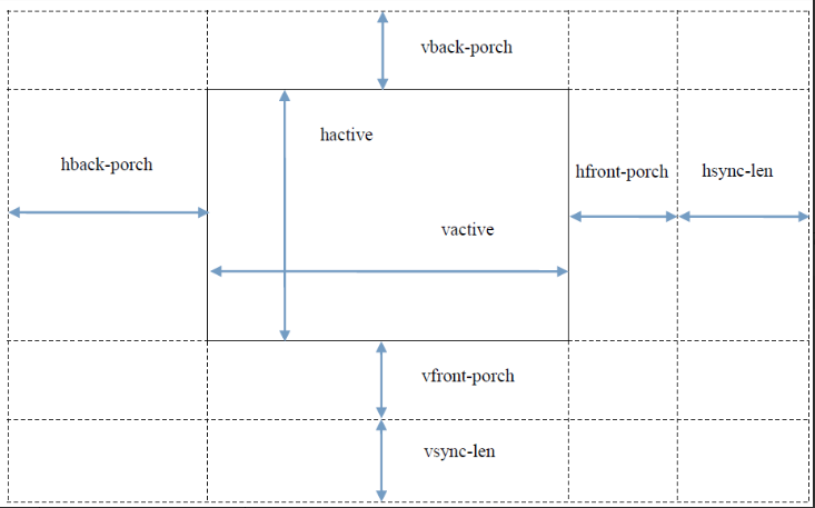
disp_timings: display-timings {
native-mode = <&timing0>;
timing0: timing0 {
clock-frequency = <120000000>;
hactive = <1088>; /* default 1080, but afbdc must 16 align */
hfront-porch = <104>;
hback-porch = <127>;
hsync-len = <4>; /////
vactive = <1920>;
vfront-porch = <4>;
vback-porch = <3>;
vsync-len = <2>; /////
hsync-active = <0>;
vsync-active = <0>;
de-active = <0>;
pixelclk-active = <0>;
};
};
};
};
- Timing Attribute Reference Figure
3.1.7 Command Format Description
		panel-exit-sequence = [
			05 05 01 28
			05 78 01 10
		];
The first three bytes of a command represent the command type, delay, and command payload length, respectively. A valid payload for the command starts on the fourth byte. The number of bytes comprising the payload needs to be equal to the command payload length (third byte).
The first byte represents two types of commands: DCS command and Generic command. The DCS command is a command specified in the MIPI standard protocol, specifically referred to as “MIPI Alliance Specification for Display Command Set.pdf”. Generic commands are generally applied to manufacturer-defined commands. Specific use of which type requires reference to screen specifications or consulting your screen factory FAE. If not specified, it is recommended to configure it according to the DCS command type.
There are three types of DCS commands: 0x05/0x15/0x39. Generic commands are classified into: 0x03/0x13/0x23/0x29.
3.1.8 Backlight
&backlight {
	pwms = <&pwm1 0 25000 0>;
	status = "okay";
};

&pwm1 {
	status = "okay";
};

&dsi {
    status = "okay";
    rockchip,lane-rate = <1000>;
    dsi_panel: panel@0 {
        status = "okay";
        compatible = "simple-panel-dsi";
        reg = <0>;
        backlight = <&backlight>;
        ...
    }
};
PWM Attributes: The PWM output used by the MIPI screen is pwm1, and the cycle frequency is 40 KHz (25,000 nano-seconds).
3.2 Main and Secondary Display Config
android 9.0 Config
device/rockchip/rk3399/rk3399.mk
PRODUCT_PROPERTY_OVERRIDES += \
    vendor.hwc.device.primary=DSI \
    #vendor.hwc.device.extend=DP
	vendor.hwc.device.extend=HDMI-A
    #vendor.hwc.device.extend=eDP
android 7.1 Config
device/rockchip/rk3399/rk3399_all.mk
PRODUCT_PROPERTY_OVERRIDES += \
    sys.hwc.device.primary=DSI \
    #sys.hwc.device.extend=DP
	sys.hwc.device.extend=HDMI-A
    #sys.hwc.device.extend=eDP
4.(HDMI or DP + MIPI)Screen Config
HDMI or DP + MIPI: This means compatible with HDMI(Main Display) + MIPI (Secondary Display) or DP(Main Display) + MIPI (Secondary Display), but does not support HDMI + DP at the same time.
4.1 Configuring DTS
android 9.0 Config
See DTS below for more details on the previous two chapters:
rk3399-khadas-edge-android.dts
4.2 Main and Secondary Display Config
android 9.0 Config
device/rockchip/rk3399/rk3399.mk
PRODUCT_PROPERTY_OVERRIDES += \
    vendor.hwc.device.primary=HDMI-A,DP\
	vendor.hwc.device.extend=DSI
5.(HDMI or DP + MIPI)Screen Config
HDMI or DP + MIPI: This means compatible with HDMI(Main Display) + MIPI (Secondary Display) or DP(Main Display) + MIPI (Secondary Display), but does not support HDMI + DP at the same time.
5.1 Configuring DTS
android 9.0 Config
See DTS below for more details on the previous two chapters:
rk3399-khadas-edge-android.dts
5.2 Main and Secondary Display Config
android 9.0 Config
device/rockchip/rk3399/rk3399.mk
PRODUCT_PROPERTY_OVERRIDES += \
    vendor.hwc.device.primary=HDMI-A,DP\
	vendor.hwc.device.extend=DSI