Connect Goodix touchscreen to VIM3

Dear all, could someone help me with Goodix I2C touchscreen connection?
I use linux-mainline-5.14

Enabled goodix module in the kernel.
Disabled i2s in /boot/env.txt

overlays=uart3 pwm_f i2c3 watchdog

Modified build/linux-mainline-5.14/arch/arm64/boot/dts/amlogic/meson-khadas-vim3.dtsi

&i2c_AO {
	status = "okay";
	pinctrl-0 = <&i2c_ao_sck_pins>, <&i2c_ao_sda_pins>;
	pinctrl-names = "default";

	khadas_mcu: system-controller@18 {
		compatible = "khadas,mcu";
		reg = <0x18>;
		#cooling-cells = <2>;
	};

	// skipped

	goodix@14 {
		compatible = "goodix,gt9110";
		reg = <0x14>;
		interrupt-parent = <&gpio>;
		// interrupts = <&gpio GPIOH_4 IRQ_TYPE_LEVEL_LOW>;
		irq-gpios = <&gpio GPIOH_4 GPIO_ACTIVE_HIGH>; // GPIOH_4 = TP_INT = 431
		reset-gpios = <&gpio GPIOZ_15 GPIO_ACTIVE_HIGH>; // GPIOZ_15 = TP_RST = 426
	};

	goodix@5d {
		compatible = "goodix,gt9110";
		reg = <0x5d>;
		interrupt-parent = <&gpio>;
		// interrupts = <&gpio GPIOH_4 IRQ_TYPE_LEVEL_LOW>;
		irq-gpios = <&gpio GPIOH_4 GPIO_ACTIVE_HIGH>; // GPIOH_4 = TP_INT
		reset-gpios = <&gpio GPIOZ_15 GPIO_ACTIVE_HIGH>; // GPIOZ_15 = TP_RST
	};
};

On VIM3 boot stage I got the following:


[    1.266302] Goodix-TS 4-0014: supply AVDD28 not found, using dummy regulator
[    1.271824] Goodix-TS 4-0014: supply VDDIO not found, using dummy regulator
[    1.377840] Goodix-TS 4-0014: i2c test failed attempt 1: -6
[    1.405826] Goodix-TS 4-0014: i2c test failed attempt 2: -6
[    1.433644] Goodix-TS 4-0014: I2C communication failure: -6
[    1.434221] Goodix-TS 4-005d: supply AVDD28 not found, using dummy regulator
[    1.440644] Goodix-TS 4-005d: supply VDDIO not found, using dummy regulator
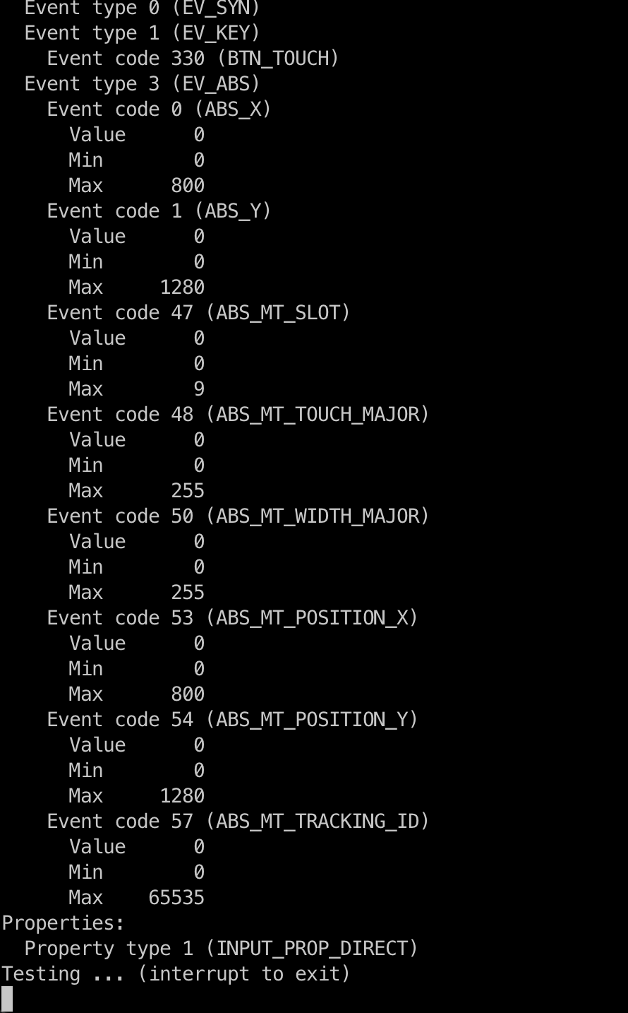
[    1.547851] Goodix-TS 4-005d: ID 9110, version: 1050
[    1.547931] Goodix-TS 4-005d: Direct firmware load for goodix_9110_cfg.bin failed with error -2

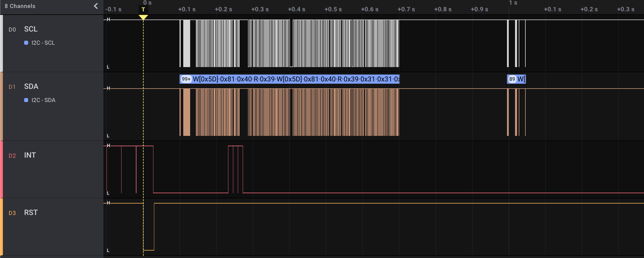
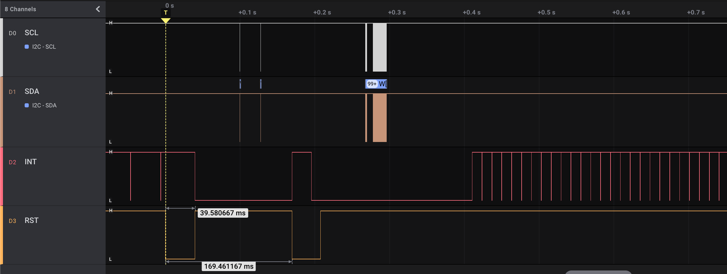
Please find an attached diagram from logic analyzer for VIM3.

goodix driver tried to drop RST line twice and reported error.

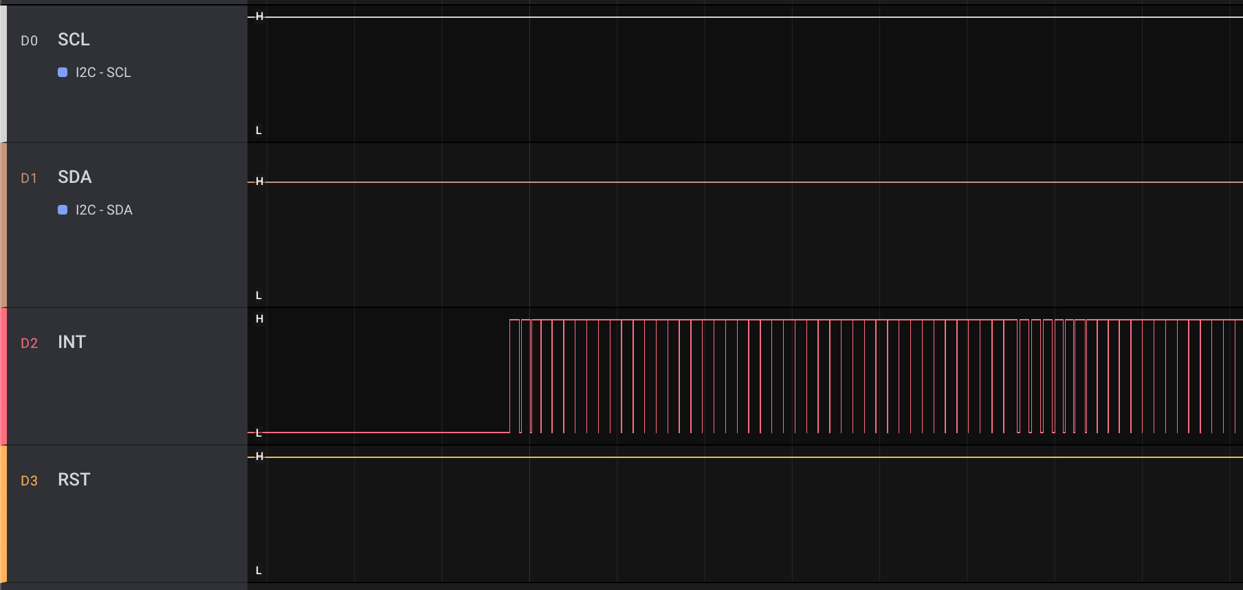
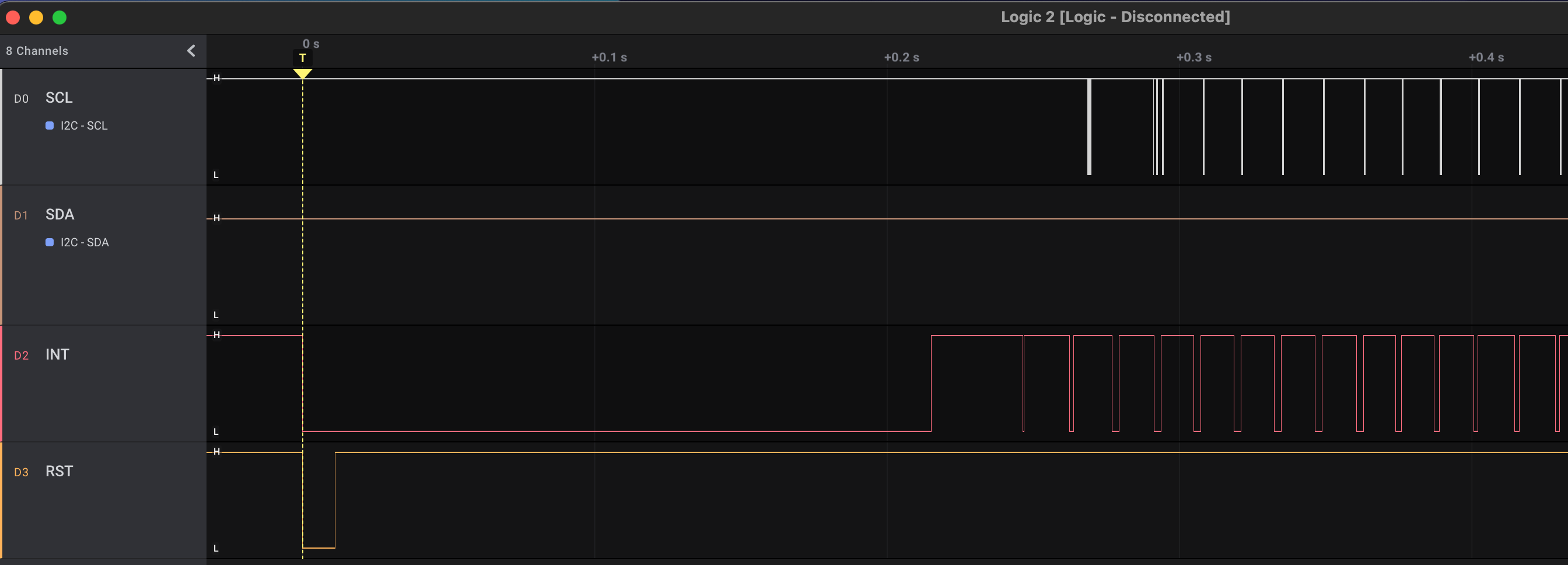
Also, I’ve attached the diagram from Arduino ESP32, that works well.
Arduino dropped RST and got an INT.
That how it should work.

In my opinion in my setup VIM3 does not process TouchPanel interrupt properly.

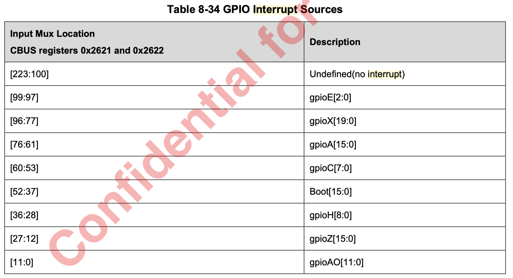
Could someone explain the proper DTS way for GPIOH_4 as an interrupt?

Honestly speaking I do not understand how to use

interrupt-parent
interrupts
irq-gpios

Thank you in advance.

Can you change the RST PIN to another one? GPIOZ_15 is OD PIN, you need to setup pull up manually.

My update.
I’ve disabled I2S and almost all unnecessary interfaces.

My device tree now looks like

	goodix@5d {
		compatible = "goodix,gt9110";
		reg = <0x5d>;
		interrupt-parent = <&gic>;
		interrupts = <0 64 0>;
		irq-gpios = <&gpio GPIOH_4 GPIO_ACTIVE_HIGH>; 
		reset-gpios = <&gpio GPIOH_7 GPIO_ACTIVE_HIGH>;
		pinctrl-names = "default";
	};

And now dmesg shows that I got an interrupt pin.

[    1.798903] Goodix-TS 4-005d: I2C Address: 0x5d
[    1.803386] Goodix-TS 4-005d: supply AVDD28 not found, using dummy regulator
[    1.810460] Goodix-TS 4-005d: supply VDDIO not found, using dummy regulator
[    1.918340] Goodix-TS 4-005d: ID 9110, version: 1050
[    1.918423] Goodix-TS 4-005d: Direct firmware load for goodix_9110_cfg.bin failed with error -2
[    1.930657] cpufreq: cpufreq_online: CPU2: Running at unlisted initial frequency: 999999 KHz, changing to: 1000000 KHz
...
[    1.944613] input: Goodix Capacitive TouchScreen as /devices/platform/soc/ff800000.bus/ff805000.i2c/i2c-4/4-005d/input/input0

Also, I see an interrupt at /proc/interrupts

cat /proc/interrupts
            CPU0       CPU1       CPU2       CPU3       CPU4       CPU5
 39:         28          0          0          0          0          0     GICv2  96 Edge      gt9110

But when I run evetest I do not see any events.

I checker TP pins using logic analyzer.
Looks like the driver starts fine.
Even if TP has 0x14 I2C address, it drops RST for a moment and addresses changes to 0x5D.


After successful init INT signal stays in low state.

Then, if I touch my TP, the INP pin generates H level and stays in the green mode.
In my opinion it’s due to unhandled interrupt.

Could someone explain me the magic regarding DT syntax of the following lines?

interrupt-parent = <&gic>;
interrupts = <0 64 0>;

Will be much appreciate.
Thank you.

Got it working.

	goodix@5d {
		compatible = "goodix,gt9110";
		reg = <0x5d>;
		interrupt-parent = <&gpio_intc>;
		interrupts = <32 IRQ_TYPE_LEVEL_LOW>; // GPIOH_4=32
		irq-gpios = <&gpio GPIOH_4 GPIO_ACTIVE_HIGH>; 
		reset-gpios = <&gpio GPIOH_7 GPIO_ACTIVE_HIGH>;
		// pinctrl-names = "default";
	};

As I understand, GPI interrupts corresponds with following.

It looks like

interrupt-parent = <&gpio_intc>;

# gpioA[15:0] [76:61]
gpioA_15 76
gpioA_14 75
gpioA_13 74
gpioA_12 73
gpioA_11 72
gpioA_10 71
gpioA_9 70
gpioA_8 69
gpioA_7 68
gpioA_6 67
gpioA_5 66
gpioA_4 65
gpioA_3 64
gpioA_2 63
gpioA_1 62
gpioA_0 61


# gpioH[8:0] [36:28]
gpioH_8	36
GPIOH_7	35
GPIOH_6	34
GPIOH_5	33
GPIOH_4	32
GPIOH_3	31
GPIOH_2	30
GPIOH_1	29
GPIOH_0	28

# gpioZ[15:0] [27:12]
gpioZ_15 27
gpioZ_14 26
gpioZ_13 25
gpioZ_12 24
gpioZ_11 23
gpioZ_10 22
gpioZ_9 21
gpioZ_8 20
gpioZ_7 19
gpioZ_6 18
gpioZ_5 17
gpioZ_4 16
gpioZ_3 15
gpioZ_2 14
gpioZ_1 13
gpioZ_0 12

# gpioAO[11:0] [11:0]
gpioAO_11 11
gpioAO_10 10
gpioAO_9 9
gpioAO_8 8
gpioAO_7 7
gpioAO_6 6
gpioAO_5 5
gpioAO_4 4
gpioAO_3 3
gpioAO_2 2
gpioAO_1 1
gpioAO_0 0

1 Like

Working DT config for TP FFC-10P connector

&i2c3 {
	status = "okay";
	pinctrl-0 = <&i2c3_sck_a_pins>, <&i2c3_sda_a_pins>;
	pinctrl-names = "default";

	// TP connector or GPIO header
	goodix@5d {
            compatible = "goodix,gt9110";
            reg = <0x5d>;
            interrupt-parent = <&gpio_intc>;
			reset-gpios = <&gpio_expander 6 GPIO_ACTIVE_HIGH>;
			
			interrupts = <66 IRQ_TYPE_EDGE_RISING>; // TP FFC pin 6 TP_INT
            irq-gpios = <&gpio GPIOA_5 GPIO_ACTIVE_HIGH>;
            
			touchscreen-swapped-x-y;
            // touchscreen-inverted-x;
            touchscreen-inverted-y;
	    };
};

1 Like