So I mentioned before in another post that I want to use the Edge in my car. My original idea was to use the Edge with the Captain and attach the LiPo battery to it so it can go into “stand by” when the car turns off. The issue I’m having is with the thought of leaving a battery in such extreme hot/cold environment. I’ll be lucky if the battery lasts a year and can you imagine if it exploded?!?!
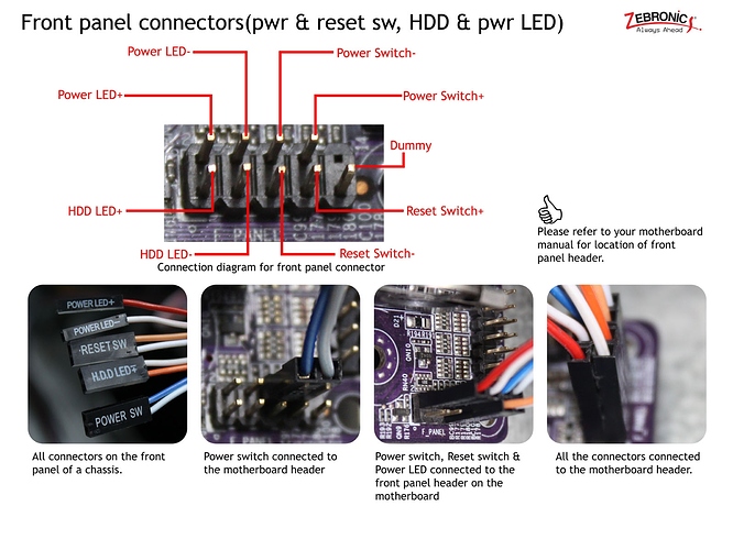
So I went back to the drawing board and started doing some more research. I found this http://www.mini-box.com/DCDC-USB-200 It’s specifically made for car computers, it even has an “Automotive mode”. All you would need to do is turn the 4 pin ATX cable into a barrel jack (super simple). It also has 2 pin cables that are for controlling the on/off on the motherboard headers. Couldn’t I just attach those cables to the GPIO somehow and tell the Edge to go into stand by when the PSU send the “off” signal? Would something like be possible in Tasker for Android?
-
In high temperature environment, the board usually needs to add heat sinks. It’s better to add fans to make it work better.
-
Automotive electronic products generally take the power supply of automobile batteries, which is unreliable to be replaced by batteries.
-
The car has an ACC lead. 12V ignites the car and 0V extinguishes the car. So you need to design another adapter board. To connect to GPIO.
-
When GPIO recognizes this level change, you can send different key values to Android, and then you process the received key values on Android.
1- using a fan is the easy part, I’m also going to use a conformal coating for more protection.
2- no idea what you are saying here
3 and 4- why use another board if that PSU can do that? I have seen people use an Arduino to do this, but why add more if I don’t need to.
To use gpio status in car i usu optron pc817
Add resistor 1k to pc817 on 1 pin pc817 2 gnd
3 and 4 pin use 330 om to gnd or +3.3 khadas and other to gpio read pin
I don’t know what you mean by the PSU, but I think it should contain what I mean by the conversion circuit. So of course you can use it.
thanks for the help!! I just have 1 or 2 more questions.
1-…whats a pc817? LOL
2- do you have a picture or maybe a small diagram?
By the sounds of it you are doing exactly what I want to do. The problem is im a noob. LOL
PSU = power supply unit
The link I posted above is of a PSU that is made for a car computer. It has 2 wires on it that connect to the “on/off” pins on a regular home computer/motherboard.
Obviously, the Edge doesn’t have front panel pins BUT it does have GPIO pins.
Does that make sense?
As long as voltage matching is available.
correct!! For powering the Edge, the PSU can do anywhere from 5v to 24V. The 2 “on/off” pins/wires are 5V. Its very simple to make that 3.3V if I have too. What I want to know is, what pins do I use on the Edge AND when the Edge gets the signal how do I tell it to go to sleep?
GPIO interrupts pins and sends a power key after identification.
I think there is a language barrier here. I feel like all you just told me was “GPIO pins do different things when you plug stuff into them”
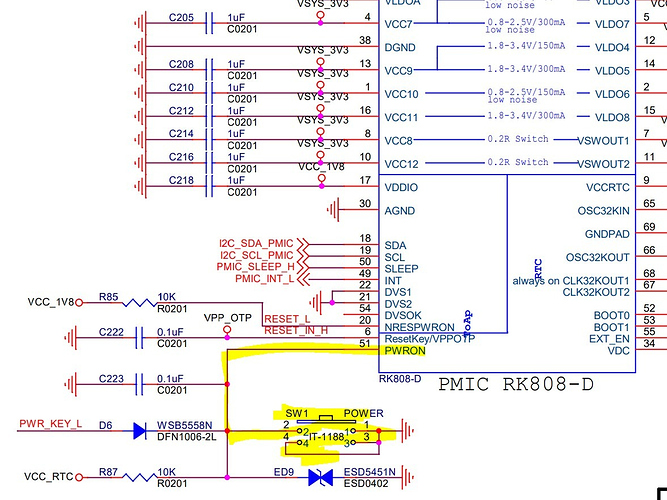
Is the onboard power button (SW1) broken out or duplicated as a pin anywhere?
drivers/input/keyboard/rk_keys.c
void rk_send_power_key(int state)
{
	if (!sinput_dev)
		return;
	if (state) {
		input_report_key(sinput_dev, KEY_POWER, 1);
		input_sync(sinput_dev);
	} else {
		input_report_key(sinput_dev, KEY_POWER, 0);
		input_sync(sinput_dev);
	}
}
Hi,
I think he’s asking if this button is accessible through a pin:
Sure, it can be simulated by listening to a GPIO pin, driver, etc., but all that requires the OS to be running, is a bunch of unnecessary complexity, and wouldn’t provide all of the same functionality as the real power button.
Has anyone figured this out yet? I would love to do the same thing but my biggest issue is a proper power supply.

