3D printable case (enclosure) for the Tone Board

Hello.

I want to share with you the design of a 3D printable box, I created for the tone board. You will find a link to the design and pictures of the printed box at the bottom of this post.

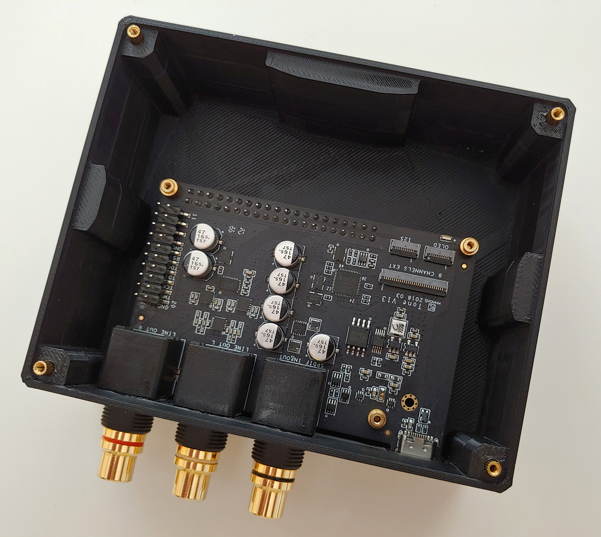
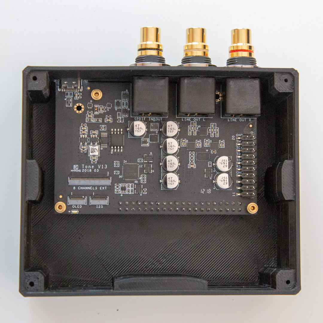
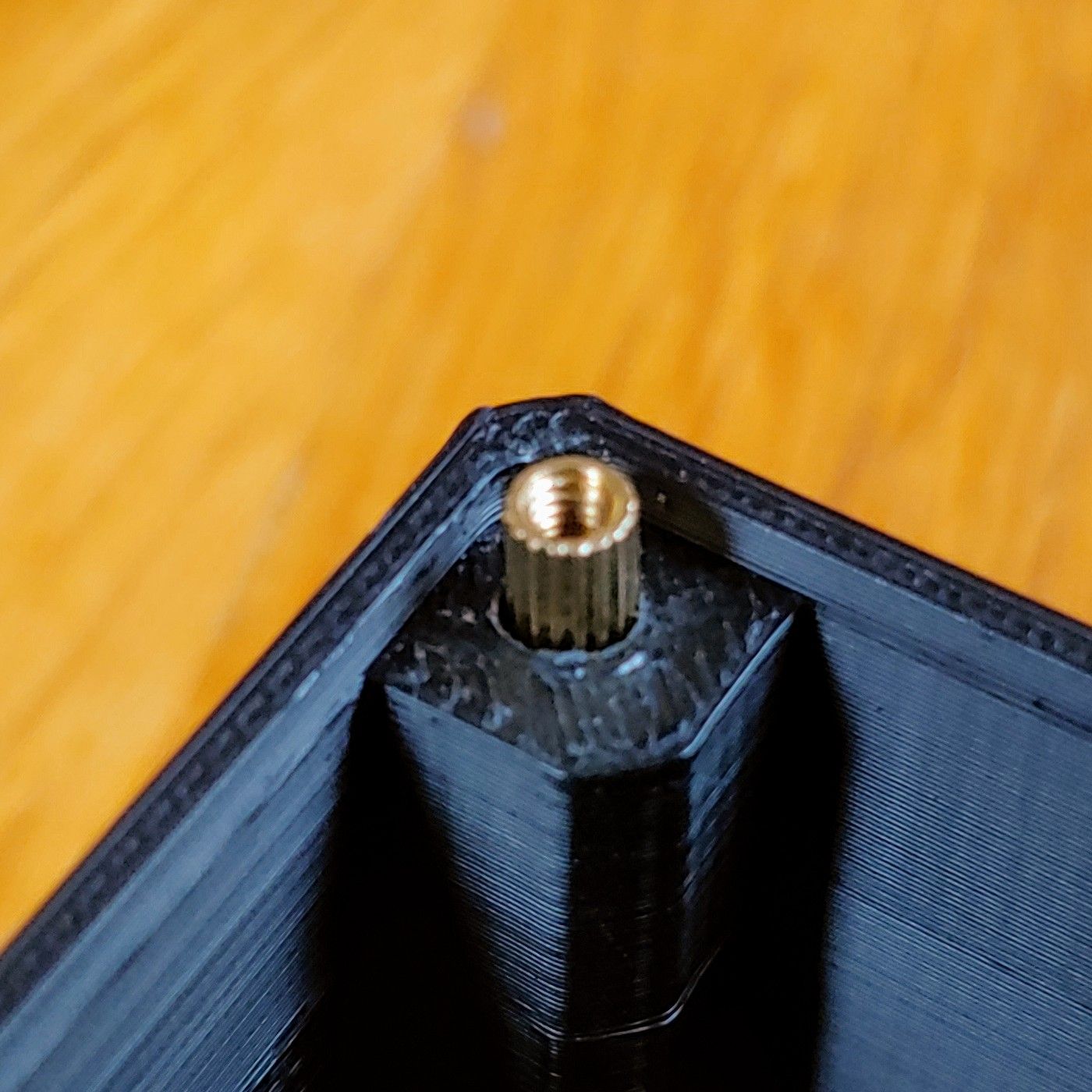
I have the VIMs edition and found out that most of the cases out there don’t fit it, as they are designed for the generic edition. This one is designed to fit both versions, using the long standoff (the 14mm one). To attach the lid, one would also need 4 additional screws.

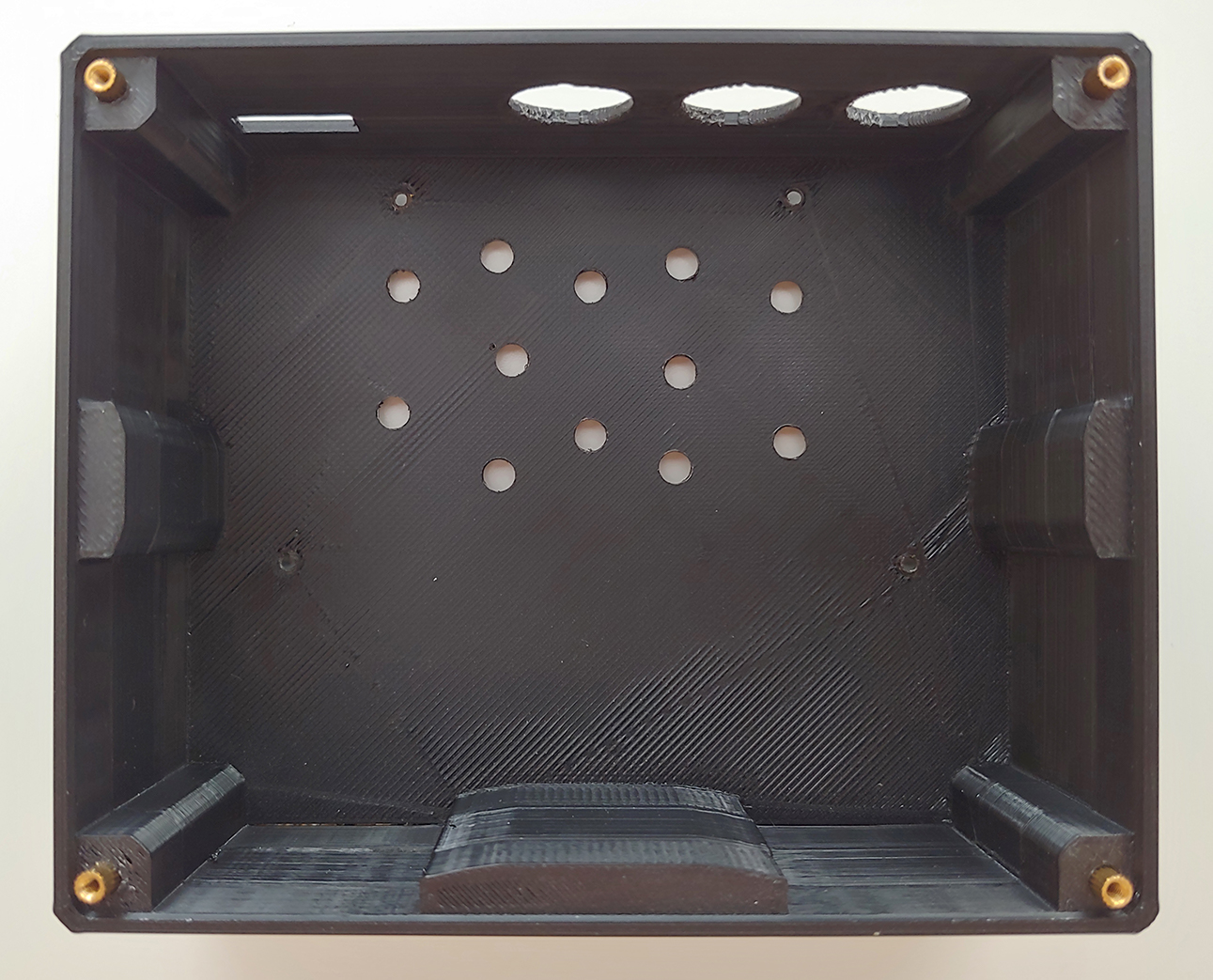
The holes for mounting the standoffs are calculated exactly as in the CAD model of the board. Depending on how accurate your printer is, you may need to adjust them a little bit for the board to fit.

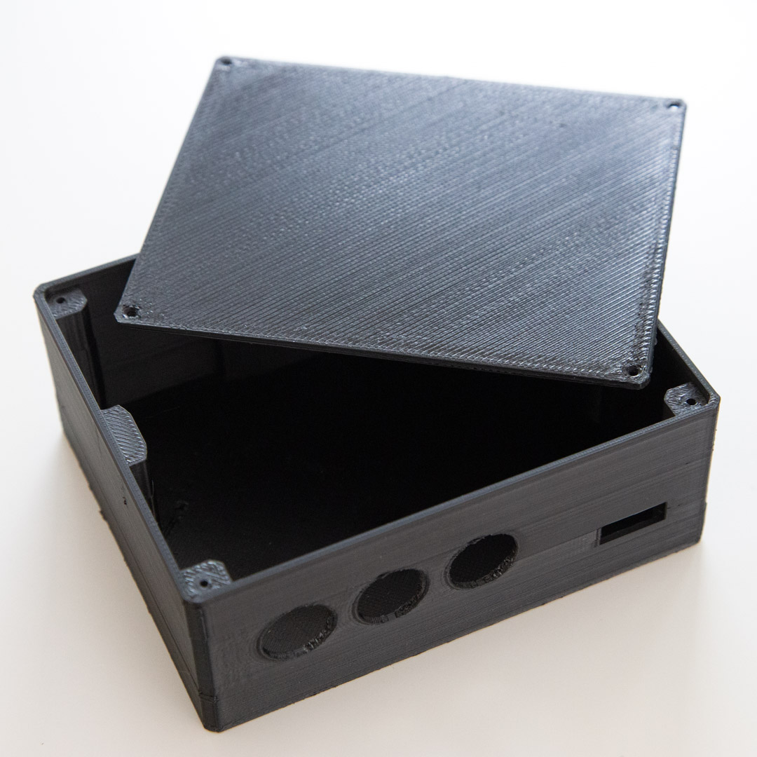
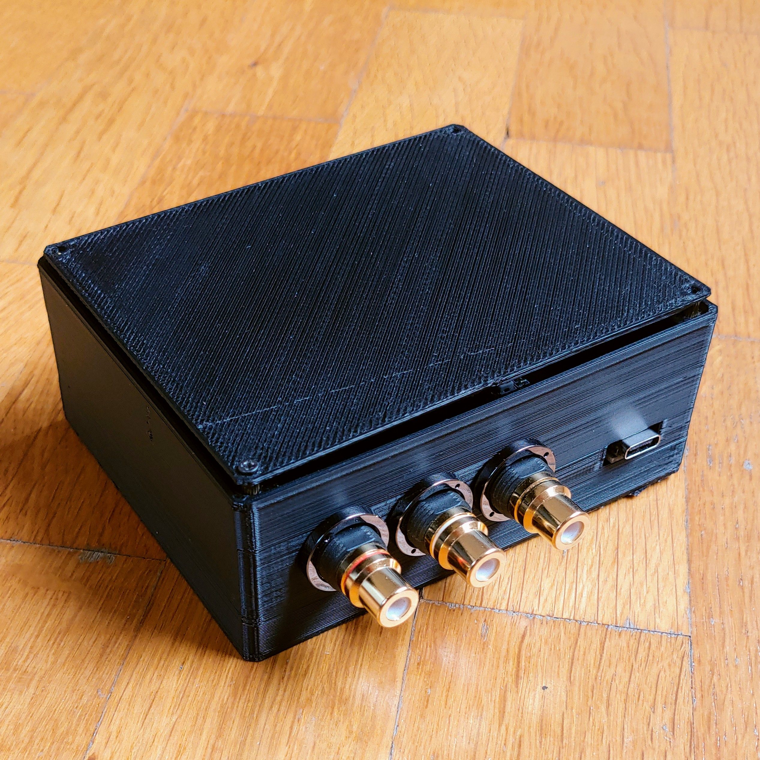
This box is intentionally designed to be a bit larger than the board itself. First, it makes it easy to mount the board inside the box. Second, it provides more weight and has a larger surface area. This makes it more stable. Before, I had my tone board in a small cardboard box. Even the weight of the cables was enough to make it fall from the table.

I used a third party service to print the board for me. They advised the use of ABS, instead of PLA, because it can sustain higher temperatures and thus the box will not be impacted from the heat emitted by the tone board.

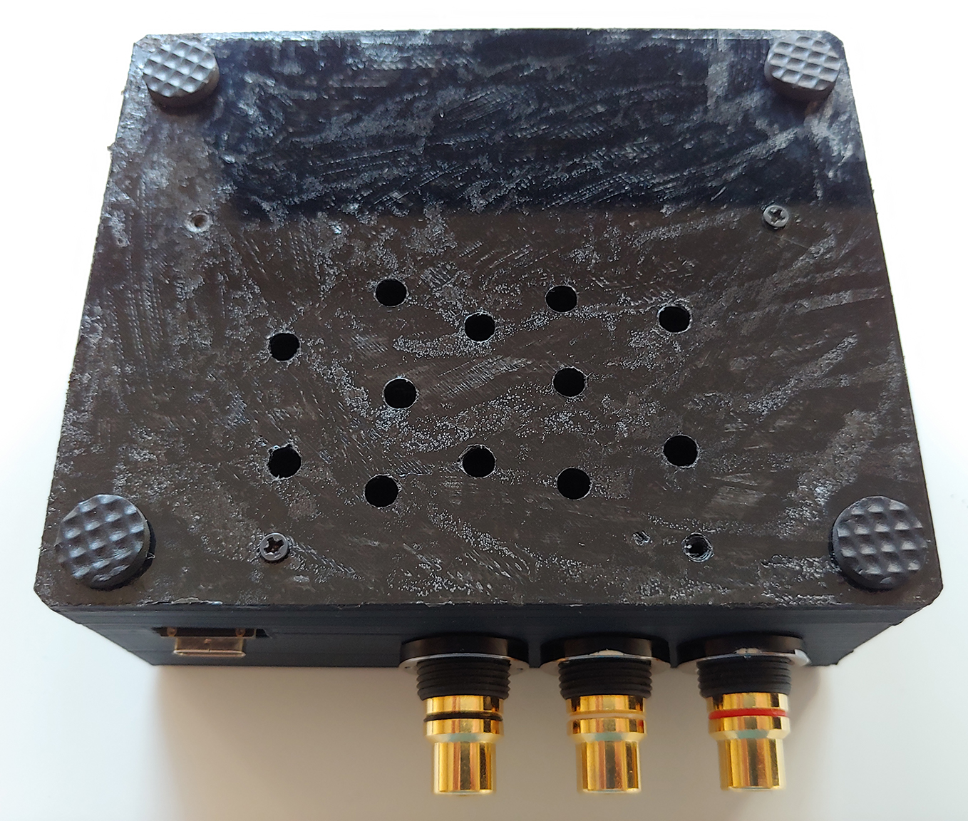
There were mixed opinions on whether the box needs holes to provide ventilation for the tone board. Some people said that it is not emitting so much heat, as to need holes for ventilation. Others thought holes are necessary, otherwise the board may be damaged inside. I would be grateful if a member of the Khadas staff can comment on that.

Here is a link to the design. It was created in TinkerCAD, so one can clone it and adjust it as they see fit. If you do so, please, share your design with the community, as well. Also, any comments, feedback and photos of prints of the case are welcome :slight_smile:

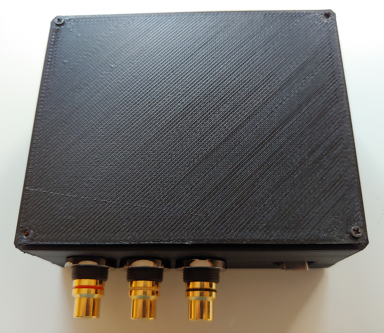
Below you can find photos of the printed case:


8 Likes

That looks cute @systemshock, nice work! From my testing of the Tone Board for Firmware v1.04, it can withstand a great deal of heat - I had it wrapped up in bubble wrap, and taped, and it worked fine for the whole day, and several of those days.

That said, I would still think some ventilation is still a good thing, if your design parameters / operating environment allows for it. Remember that for electronics components under prolonged thermal-stress, there will be material creep, especially at the junctions - Therefore to ensure a long service life, it is good to keep the temperatures down. It’s kinda like, sure you can run your CPU overclocked for maybe 1-2 years, but if you didn’t overclock it, maybe it could last 3-5 years.

Your casing is interesting, as (1) it is made of plastic, which isn’t a good natural conductor of heat. However, (2) I notice that it has a large-cavernous empty space within it, which would allow for “internal convection” of heat from the components to the plastic outer surface. However, yes it wouldn’t be as effective as a cavernous metal casing without holes.

You can always design some narrow slits into the sides closest to the walls (both on the top and bottom sides), so that they don’t look too obvious. Take a look at router designs, they often employ passive-cooling solutions that look quite pleasant. Observe the presence of the narrow slits near the casing walls.

router1x1

By the way, you can also post your design to thingiverse.com, and link it back to this forum post. :slight_smile:

2 Likes

Hello, @tsangyoujun and thank you for the reply!

I made a little modification to the assembly of the case and now it allows for ventilation. In short, I used the 4 extended standoffs, that came with the case, to raise the lid. However, since I found them to raise it way too much, I made a deburring to sink them in. Here is how to do it:

I used a pair of drill bits – 2mm and 3mm. They are made for wood, but I have found out they work quite well with plastic too. I did not use a power drill, as the plastic is very soft and the amount of drilling that needs to be done is very small. Instead I used a small screwdriver and drilled by hand. As I found out, it is so easy to drill, that one can do it without the screwdriver too; just by holding the bit.

I used the 2mm drill to enlarge the diameter of the holes in the corners of the box. They were a bit tight in the printed box. Then I used the 3mm drill to create a small deburring, so that the standoff can sink in. Drilling with the 3mm bit inserted pieces of plastic in the 2mm hole underneath. So, I had to use the 2mm again, to help clear it out. I repreated this process several times, proceeding in small steps, until I was satisfied with the height. You can raise the lid as much as you want. Here is what the end result looks like:

When you get all 4 standoffs in place and sunk at even length, you simply attach the lid on top of them. Here is what the box looks like now. I still have not bought additional screws, so I used one of the 4 supplied with the tone board, to fix the lid. Hopefully I will get some time to go to the local shop and buy a few soon :slight_smile:

And here is the box, standing on top of the JDS atom. The white thing in the back is an IKEA FÖRSIKTIG, which I am using as a €2 monitor stand, lol :laughing:.

3 Likes

Neat! Looks like a Mini JDS Atom, haha!

Oh it could help if there are some holes on the bottom too - so that cold air can go in via the bottom, and leave via the top.

Nice work, appreciate it! I would repost it on our social media, however the #VIM3 campaign is in full swing right now. I’ll repost your design work after the campaign.

Thank you @systemshock :slight_smile: (I was secretly waiting for someone to 3d print a case, hence the post with the CAD files, hehe)

1 Like

@tsangyoujun, thank you for the advice! When I get some spare time, I will modify the design of the box, to include such holes on the bottom. Meanwhile, if someone prints the box, they can just drill a few small holes on the bottom of the box. The plastic is really easy to work with, it is quite soft.

1 Like

I finally got some spare time and added the holes to the bottom of the case. You can see them on the pictures below. The idea was to have them exactly under the board, so that when the air enters the case, it will go up and then around the board, on it’s way out. As seen on the second screenshot, there are no other holes and the only way for air to enter the case is under the board. I hope that this will improve ventilation.

The holes were drilled by hand, using a 4mm drilling bit attached to a screwdriver. The plastic is very soft and allows for this.

In the next days, when I get some spare time, I will update the 3D model to include the holes on the bottom. I will also provide a short instruction on how to assemble the board using the standoffs, so that proper ventilation is provided. I will also update the first post to include proper information.

P.S. There is another thing that occurred to me, regarding the assembly of the board in the case. It is pretty obvious, but I didn’t think of it back then, when I first posted about the case. If one does not have additional M2 screws, it is possible to do only with the original 4 that come with the board. You just use two on the bottom and two on the top, attached diagonally, like this:

2 Likes