Do you see your connector’s pinouts here?
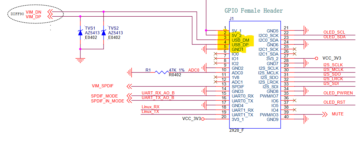
Tone Board GPIO pin assignments…
+5 volt Pin 2
DM Pin 3
DP Pin 4
GND Pin 5
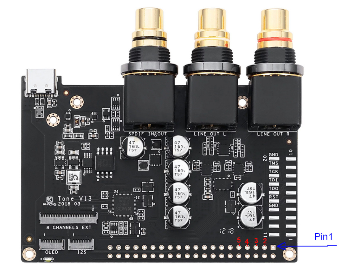
Tone Board GPIO…
Do you see your connector’s pinouts here?
Tone Board GPIO pin assignments…
+5 volt Pin 2
DM Pin 3
DP Pin 4
GND Pin 5
Tone Board GPIO…