Have anybody experimented with connecting LED boards to the GPIO pins? I want to use the camera with IR LEDs connected straight onto the pins. Or with a camera similar to what is available for raspberry pi:
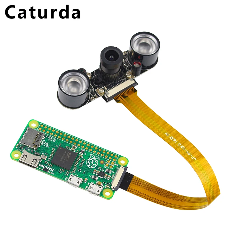
use the khadas OS08A10 camera,
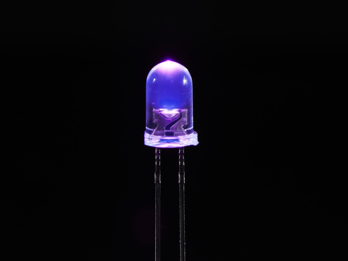
Get rid of the IR cut stuff, add some IR LEDs powered off the GPIO, maybe connect it to one of the GPIO pins for things like switching on/off if you will…
and you have yourself a Handy 4K CCTV camera…
1 Like
hello, why come up with something when there is a proprietary camera from Khadas 
Also @Makro
if you used other cameras, you’d need to make modifications to the system files, like Device tree etc. Unless your application really requires that specific camera and your willing to go through the sacrifice of making it work, I would recommend that you’d get your self the Khadas camera itself, and try those Instructions I gave above…
also, you’d need to find the camera module that is compatible in on itself, so best luck with that as well
Whatever it is, we will try to help you with your project.
best of luck mate
only need to specify OS 
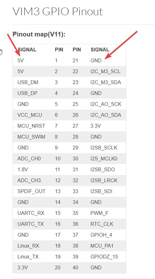
I do use the OS08A10 camera module, and have set it to only have IR function enabled. I am running android and now trying to find a small IR led board to connect to these 5V and GND pins. The guide is not that user friendly for beginners:
Hmm, you’d use Android to run a CCTV camera ?
deep inhale

Shouldn’t be that hard…
It is just two GPIO pins with a 5v difference…
how do you plan to attach the LED ?
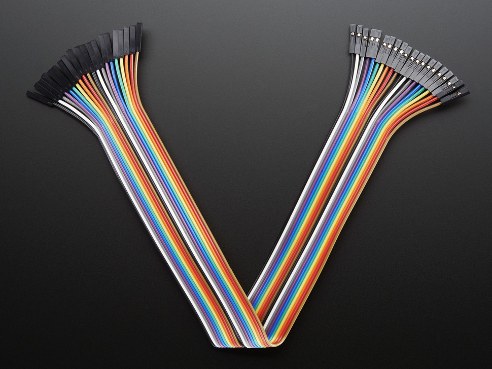
I suggest using some breadboard Jumper wires like this…
Make sure your LED can withstand 5v btw, most small LEDs are rated 3.3v max…
you should probably connect it to the 3.3v line… or use a little 220Ω resistor in parallel…
1 Like
Led will of course fit the output 
It’s not just a cctv, that’s the simplified version for explaining the concept. Although I am looking into running Linux on the device instead.
You should highly consider using linux…, you would have better control over it…
what is the application, if not private, please elaborate, don’t be scared, I can understand stuff very easily 
1 Like
You seem to only know how to tell fairy tales! when will you please us with your work?

gee golly thanks mister !
aww, so cute the way you ask, unfortunately, I’ve got nothing in store for you right now, check in later, I will show you something ![]()
Don’t worry, you don’t need to make an effort, I already like your beautiful stories from the world of fantasy, continue …


Weird request, I dig that
okay, let’s talk about that later, we need to help with @Makro’s project
*unless he considers our help ample enough…
Of course he needs help, how do you plan to help him?
The application use firebase, if switching over to Linux, I wonder if firebase can still be used for p2p webrtc call notifications. The device accepts calls from a certified user, it sends a videostream and logs the call in an admin panel. In the admin panel you can manage users and camera units. The service is multi tenant. Thats pretty much it.
if your going for an app, with the p2p video streaming capablity, you could have mentioned that earlier,
In that case, it might be better to stick with android, as your overall operating environment would be better…
also note that you could utilize the Hardware encode/decode capability with Android…
which Linux does not offer at the moment…
1 Like
Reverse bias kills LEDs, running them the correct way round then the voltage drop over the LED is the one defined in the data sheet, with the rest of the voltage dropped over the resistor you put in series with it. Current thru the LED and resistor are the same, so you adjust the resistance of the series resistor to get the current you want as you know the voltage (supply - LED voltage drop), you know the current you want (from datasheet) and so you calculate the resistor with R=V/I. So its incorrect to say that LEDs are 5v or 3.3v tolerant
So to answer @Makro question - join the Anode of you LED to the +5v GPIO in, join one side of a resistor to the cathode of your LED and then the other side of the resistor to the 0v GPIO pin if you want the LED permanently, and calculate the resistance as above
1 Like