Hello again!
Since yesterday I’d been investigating and searching information around this community and I found some interesting post that shed some light on the matter.
About this post by @Beir8 (How to access GPIO on Android pie?) I clarified that there is a way to configure more than one pin of the 40-pin GPIO header to make them work as digital input/output on Android Pie. Additionally, @Beir8 's post explains how to modify files in kernel to achieve that GPIO functionality. In there it indicates that it’s necessary to rebuild the Android image to apply that settings. I’ve never done this so I searched on the forum again and I found a related topic where it’s explained how to do it (Building Android Pie for VIM3).
In my application I would like to use the 6 yellow highlighted pins:
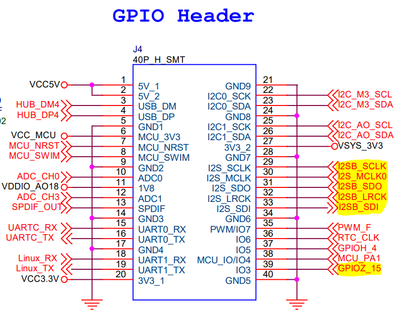
Five of them are used for I2S audio, but I think that they can be defined for GPIO as we can see here:
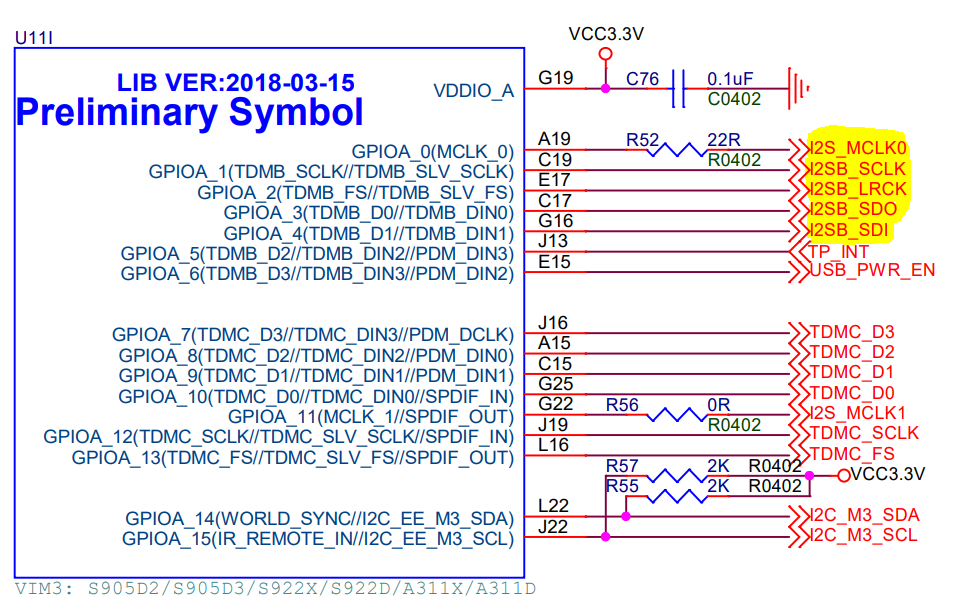
On the other hand, in one of the above mentioned post I found that @quatro explains how it’s posible to disable I2S audio to gain access to pins 29 to 33. The last one (pin 39) I think that is already available by default for GPIO. Therefore, my goal is for the pins to be as follows:
PIN 29 - GPIOA_1
PIN 30 - GPIOA_0
PIN 31 - GPIOA_3
PIN 32 - GPIOA_2
PIN 33 - GPIOA_4
PIN 39 - GPIOZ_15
At this point a question arises for me:
- How do we calculate the GPIO number list for those pins export?
I would appreciate any suggestion to achieve my objective or any recommendation on that topic. Thanks in advance!