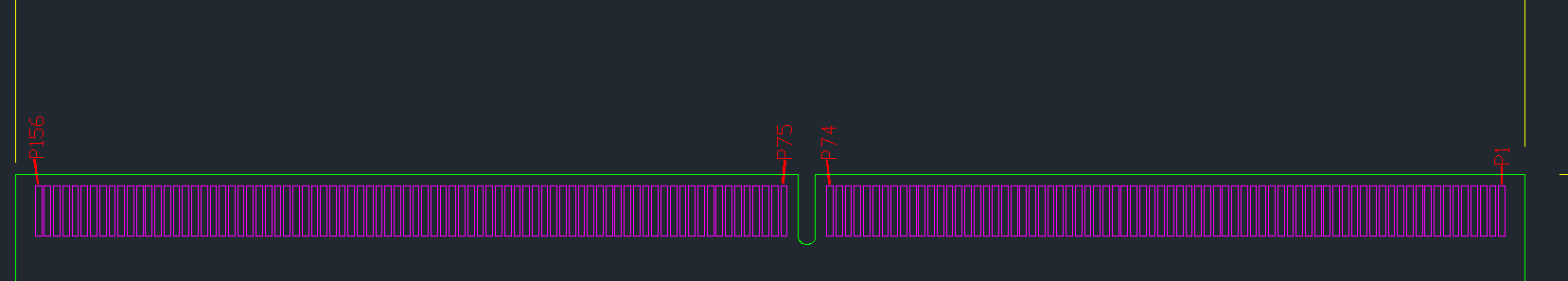
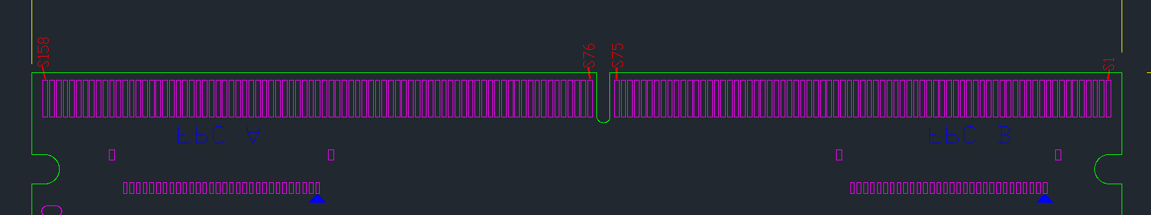
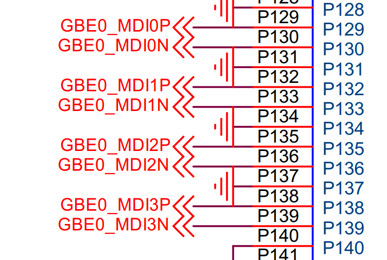
We are designing a custom board for Khadas Edge, unfortunately, I was not able to find any info regarding the pinout of MXM3 connector on the Captain - only information about pinout is in the schematic of the Captain board and in the schematic of the EDGE, but where on the connector do you physically have pin P1, S1, P75, P76? What is the order of the pin numbering? Connector pin numbering is not an industry standard and I think that the manufacturer should provide this information.
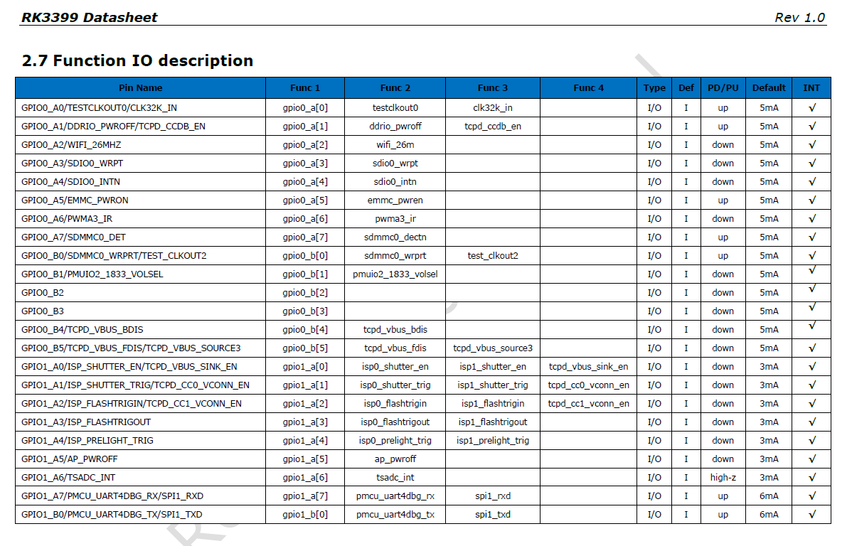
What are the pin types (input/output/pin mux), power (voltage, amps) specification of individual supply rails, info about internal pull-ups/downs… I am generally asking for some hardware documentation that does not suck. Hopefully some design guides.
I downloaded .brd file of the captain board, opened it in Allegro free physical viewer, but it does not contain any information. Just outline of the PCB and position of the MXM3 connector. Pin names/numbers are not visible.
Are you able to provide any of this information? Thank you.
Thank you very much. It would be nice to have some kind of design guide (PDF), which includes all of this information so people who would like to create their own boards have it in one place so they do not have to reverse-engineer everything (yeah, it is possible to estimate pin numbering from schematic and PCB with multimeter, but you know…). Just a tip.