I have tried your suggestion but still my display is not getting on.
With lcd_exist = 1 only backlight led gets on.
I have changed the parameters in my .dtsi file but still it is not getting on.
I am getting following errors while connecting my display.
lcd[31m: error: failed to get dsi_init_on
lcd[31m: error: failed to get dsi_init_off
lcd[0m: failed to get power_on_step
lcd[0m: failed to get power_off_step
But I have used the same parameters which I used in Khadas Edge V where my display is working.
You need to fill your lcd parameters in these.
1 Like
I got something on the display when I connected the HDMI to VIM3. So, If I connect only my MIPI DSI display to VIM3 then I was able to see only flickering on the display but If I connect MIPI DSI and HDMI together with the VIM3 then I was able to see the android homepage (still it is not stable) on my MIPI DSI display.
Though it isn’t perfect but at least I was able to see something.
Is there any relation between MIPI DSI and HDMI?
Do I need to check the primary display settings?
rockchip and amlogic,The main difference lies in the configuration of timing parameters.
You can paste both timing parameters to me, or you can adjust the timing parameters by yourself.
Note that it is not an initialization register parameters.
My MIPI DSI Configuration in Amlogic:
lcd{
compatible = “amlogic, lcd-g12b”;
mode = “tablet”;
status = “okay”;
key_valid = <0>;
clocks = <&clkc CLKID_MIPI_DSI_HOST
&clkc CLKID_MIPI_DSI_PHY
&clkc CLKID_DSI_MEAS_COMP
&clkc CLKID_VCLK2_ENCL
&clkc CLKID_VCLK2_VENCL
&clkc CLKID_GP0_PLL>;
clock-names = “dsi_host_gate”,
“dsi_phy_gate”,
“dsi_meas”,
“encl_top_gate”,
“encl_int_gate”,
“gp0_pll”;
reg = <0x0 0xffd07000 0x0 0x400 /* dsi_host /
0x0 0xff644000 0x0 0x200>; / dsi_phy /
interrupts = <0 3 1
0 56 1>;
interrupt-names = “vsync”,“vsync2”;
pinctrl_version = <2>; / for uboot /
clk_path = <1>; / default gp0 pll */
	/* power type:
	 *    (0=cpu_gpio, 1=pmu_gpio, 2=signal,3=extern, 0xff=ending)
	 * power index:
	 *    (point gpios_index, or extern_index,0xff=invalid)
	 * power value:(0=output low, 1=output high, 2=input)
	 * power delay:(unit in ms)
	 */
	 /*
	lcd_cpu-gpios = <&gpio GPIOH_4 GPIO_ACTIVE_HIGH
			&gpio GPIOH_7 GPIO_ACTIVE_HIGH>;
	lcd_cpu_gpio_names = "GPIOH_4","GPIOH_7";
	*/
	lcd_expander_gpio_names = "LCD_RESET","LCD_EN";

	lcd_1{
		model_name = "TS050";
		interface = "mipi";
		basic_setting = <1280 800 /*h_active, v_active*/
			1370 813 /*h_period, v_period*/
			8 /*lcd_bits*/
			64 118>; /*screen_widht, screen_height*/
		lcd_timing = <32 80 0 /*hs_width, hs_bp, hs_pol*/
			6 14 0>; /*vs_width, vs_bp, vs_pol*/
		clk_attr = <0 /*fr_adj_type(0=clk, 1=htotal, 2=vtotal)*/
			0 /*clk_ss_level */
			1 /*clk_auto_generate*/
			71000000>; /* 47 pixel_clk(unit in Hz)*/
		mipi_attr = <4 /*lane_num*/
			300 /* 440 bit_rate_max(MHz)*/
			0 /*factor(*100, default 0 for auto)*/
			1 /*operation_mode_init(0=video, 1=command)*/
			0 /*operation_mode_display(0=video, 1=command)*/
			1 /*
			   *video_mode_type
			   *(0=sync_pulse,1=sync_event,2=burst)
			   */
			1 /*clk_always_hs(0=disable,1=enable)*/
			0>; /*phy_switch(0=auto,1=standard,2=slow)*/

		/* dsi_init: data_type, num, data... */
		dsi_init_on = <

			0xFF 0>;   /*ending*/
		dsi_init_off = <

			0xff 0>;    /*ending*/

		extern_init = <0xff>; /*0xff for invalid*/

		/* power step: type, index, value, delay(ms) */
		power_on_step = <
			4 1 1 60
			4 0 1 10
			4 0 0 10
			4 0 1 10
			2 0 0 0
			0xff 0 0 0>; /*ending*/
		power_off_step = <
			2 0 0 0
			4 0 0 0
			4 1 0 20
			0xff 0 0 0>; /*ending*/
		backlight_index = <0>;
	};
};
My MIPI DSI Configuration in Rockchip:
&dsi {
status = “okay”;
rockchip,lane-rate = <440>; //1000 --> 600 -->490
dsi_panel: panel@0 {
status = “okay”;
compatible = “simple-panel-dsi”;
reg = <0>;
backlight = <&backlight>;
reset-gpios = <&gpio4 RK_PD4 GPIO_ACTIVE_HIGH>; /* GPIO4_D4 /
enable-gpios = <&gpio4 RK_PD5 GPIO_ACTIVE_HIGH>; / GPIO4_D5 */
// pinctrl-names = “default”;
// pinctrl-0 = <&lcd_reset_gpio>, <&lcd_enable_gpio>;
reset-delay-ms = <10>;
enable-delay-ms = <60>;
prepare-delay-ms = <60>;
unprepare-delay-ms = <60>;
disable-delay-ms = <60>;
dsi,flags = <(MIPI_DSI_MODE_VIDEO | VID_MODE_TYPE_BURST |
MIPI_DSI_MODE_LPM | MIPI_DSI_MODE_EOT_PACKET )>;
	dsi,format = <MIPI_DSI_FMT_RGB888>;
    dsi,lanes  = <4>;
    panel-init-sequence = [

	];
	panel-exit-sequence = [

	];

    disp_timings: display-timings {
        native-mode = <&timing0>;
        timing0: timing0 {
            clock-frequency = <66000000>;
            hactive = <1280>; /* default 1080, but afbdc must 16 align */
            hfront-porch = <60>;
            hback-porch = <10>;
            hsync-len = <20>;
            vactive = <800>;
            vfront-porch = <8>;
            vback-porch = <2>;
            vsync-len = <3>;
            hsync-active = <0>;
            vsync-active = <0>;
            de-active = <0>;
            pixelclk-active = <0>;
        };
    };
};
};
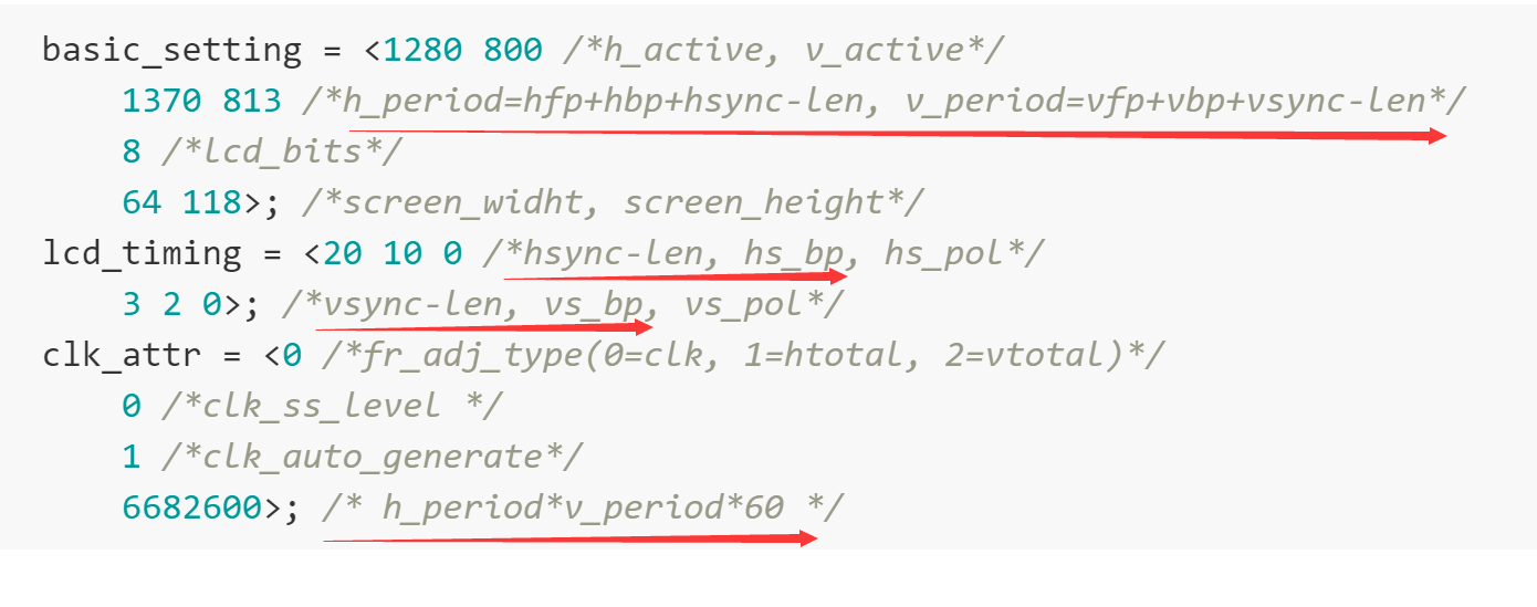
		basic_setting = <1280 800 /*h_active, v_active*/
			1370 813 /*h_period=hfp+hbp+hsync-len, v_period=vfp+vbp+vsync-len*/
			8 /*lcd_bits*/
			64 118>; /*screen_widht, screen_height*/
		lcd_timing = <20 10 0 /*hsync-len, hs_bp, hs_pol*/
			3 2 0>; /*vsync-len, vs_bp, vs_pol*/
		clk_attr = <0 /*fr_adj_type(0=clk, 1=htotal, 2=vtotal)*/
			0 /*clk_ss_level */
			1 /*clk_auto_generate*/
			66828600>; /* h_period*v_period*60 */
1 Like
I tried to change the bit rate(of MIPI DSI) from dtsi but It does not change at all.
I get 433 MHz of bit rate every time. It seems to be hardcoded.
From where do I change the bit rate of MIPI DSI?
I am sharing my dtsi value:
mipi_attr = <4 /lane_num/
200 /* 440 bit_rate_max(MHz)*/
Can your LCD display normally? Why did you want to change the bit rate? How did you confirm that it did not take effect?
I check the logs after changing in dtsi file but still, I get 433 MHz every time.
Why it is not changing with respect to the value of dtsi file?
dmesg logs:
[ 0.000000] <6>[ 0.000000@0] lcd: panel_type: lcd_1
[ 0.000000] <6>[ 0.000000@0] lcd: lcd_ctrl: 0x00000083
[ 0.000000] <4>[ 0.000000@0] jason lcd_exist: 1
[ 1.481996] <6>[ 1.481996@2] lcd: driver version: 20200102(6-g12b)
[ 1.569087] <6>[ 1.569087@2] [bc001b74+ 64][] lcd_ioremap+0xf8/0x1e4
[ 1.575126] <6>[ 1.575126@2] [bc001bb4+ 64][] lcd_probe+0x234/0x878
[ 1.736038] <6>[ 1.736038@2] [bc001cbc+ 16][] lcd_init+0x1c/0x38
[ 1.772016] <3>[ 1.772016@4] lcd: error: lcd_ioremap: reg map failed: 0x0
[ 1.777536] <6>[ 1.777536@4] lcd: detect mode: tablet, fr_auto_policy: 0, key_valid: 0
[ 1.784172] <6>[ 1.784172@4] lcd: detect lcd_clk_path: 1
[ 1.788421] <6>[ 1.788421@4] lcd: lcd_clktree_probe
[ 1.791772] <6>[ 1.791772@4] lcd: status: 3, init_flag: 0
[ 1.795900] <6>[ 1.795900@4] vout: vout1: register server: lcd_vout_server
[ 1.801503] <6>[ 1.801503@4] vout: vout2: register server: lcd_vout2_server
[ 1.807183] <6>[ 1.807183@4] lcd: lcd_get_config from dts
[ 1.811307] <6>[ 1.811307@4] lcd: no range_setting
[ 1.814823] <4>[ 1.814823@4] lcd_expander_gpio_probe…
[ 1.818738] <4>[ 1.818738@4] lcd_expander_gpio_probe…
[ 1.822661] <4>[ 1.822661@4] lcd_expander_gpio_probe…
[ 1.826615] <4>[ 1.826615@4] lcd_expander_gpio_probe…
[ 1.830543] <4>[ 1.830543@4] lcd_expander_gpio_probe…
[ 1.834484] <4>[ 1.834484@4] lcd_expander_gpio_probe…
[ 1.838411] <6>[ 1.838411@4] lcd: TS050, mipi, 8bit, 1280x800
[ 1.842887] <6>[ 1.842887@4] lcd: pixel_clk = 6.671MHz, bit_rate = 433.615MHz
[ 1.862752] <6>[ 1.862752@0] lcd: lcd_probe ok
[ 3.429159] <6>[ 3.429159@0] lcd: clk_gate is already on
[ 3.943004] <6>[ 3.943004@0] lcd vlock_en=1, vlock_mode=0x4
Would you please look at this problem?
I want to know the exact number of pin ‘TP_RST’ (which goes into gpio expander TCA6408).
How do I pass the pin number of TP_RST in dts?
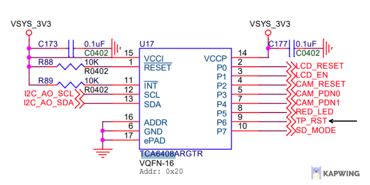
My TP_RST pin is not getting low.
I have calculated the number of TP_RST pin as:
Bank Number 496 + Pin Number 5 = 501
Is it correct?
The TP_RST is not connected to CPU soc, you can’t get the value from the bank.
You can refer to this
@Terry
Yes, I saw that. My MIPI DSI Display is on but my touch driver is not working. My driver requires pin number of the reset pin(TP_RST).
DTS Snippet:
irq_gpio = <465>;
rst_gpio = <502>; <-------- (What should I write here???)
hid_desc_register = <1>;
Error Logs:
xres: RESET CYTTSP gpio=502 r=0
reset_and_wait: reset timed out
startup_: Error on h/w reset r=-62
xres: RESET CYTTSP gpio=502 r=0
reset_and_wait: reset timed out
startup_: Error on h/w reset r=-62
xres: RESET CYTTSP gpio=502 r=0
reset_and_wait: reset timed out
startup_: Error on h/w reset r=-62
I’m very sorry for my mistake, I thought you were talking about the MIPI LCD.
About the touch driver, you can refer to the touch driver file
tca6408_output_set_value(TCA_TP_RST_MASK, TCA_TP_RST_MASK);
1 Like
Thank You for your help.
I got my touch driver working.