BarryS:
[ 1.572086] rockchip-pinctrl pinctrl: pin gpio4-23 already requested by ff940000.hdmi; cannot claim for ff970000.edp
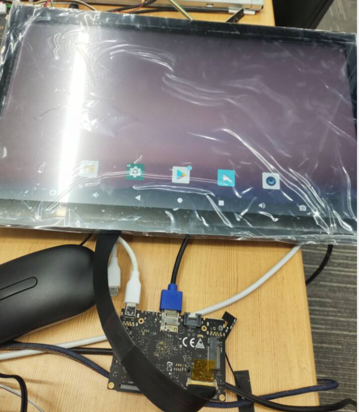
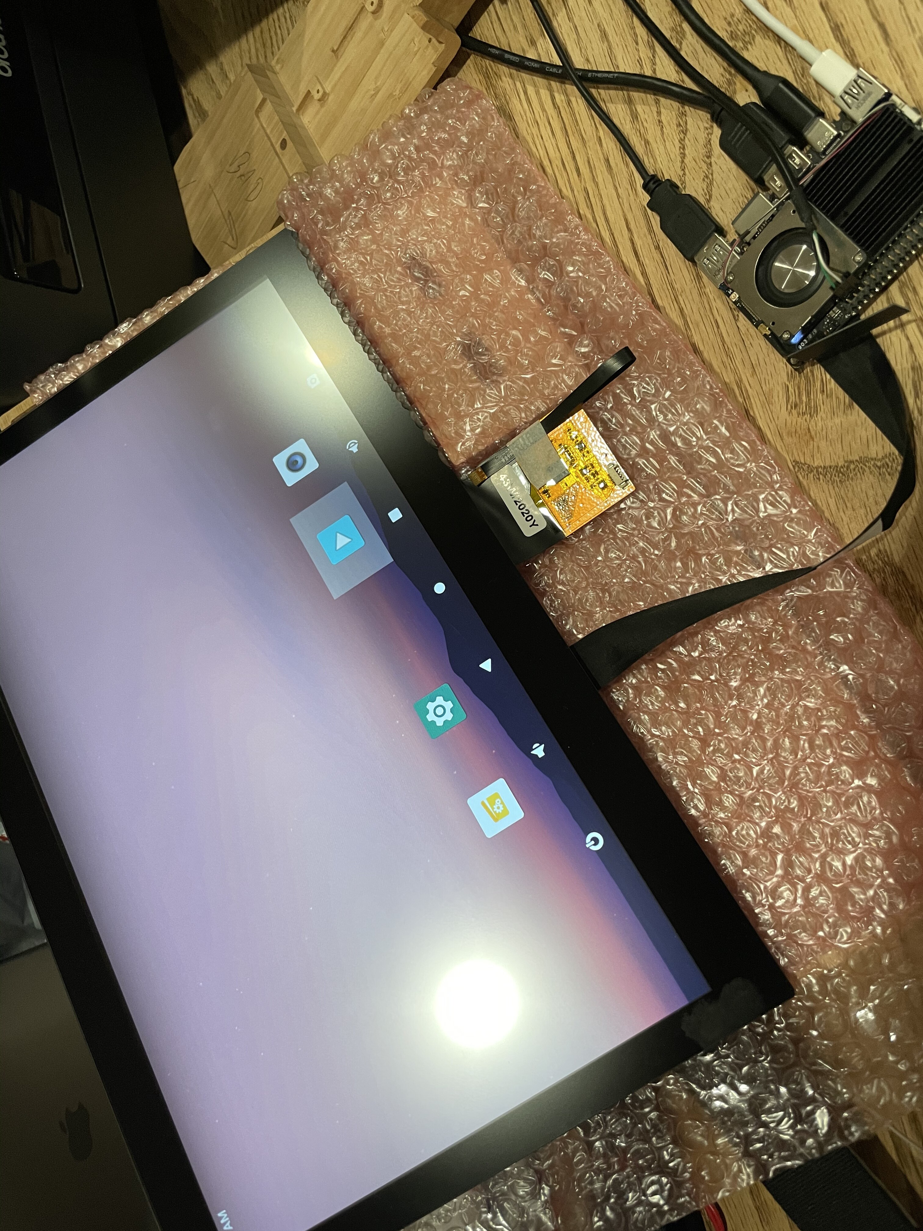
Edge android 10.0
hlm@Server:/users/hlm/Rockcip_Android10.0_SDK/kernel$ git diff arch/arm64/boot/dts/rockchip/rk3399.dtsi
diff --git a/arch/arm64/boot/dts/rockchip/rk3399.dtsi b/arch/arm64/boot/dts/rockchip/rk3399.dtsi
index 6311964..0980dcd 100755
--- a/arch/arm64/boot/dts/rockchip/rk3399.dtsi
+++ b/arch/arm64/boot/dts/rockchip/rk3399.dtsi
@@ -2152,10 +2152,8 @@
                compatible = "rockchip,rk3399-edp";
                reg = <0x0 0xff970000 0x0 0x8000>;
                interrupts = <GIC_SPI 10 IRQ_TYPE_LEVEL_HIGH 0>;
-               clocks = <&cru PCLK_EDP>, <&cru PCLK_EDP_CTRL>, <&cru PCLK_VIO_GRF>;
-               clock-names = "dp", "pclk", "grf";
-               pinctrl-names = "default";
-               pinctrl-0 = <&edp_hpd>;
+               clocks = <&cru PCLK_EDP>, <&cru PCLK_EDP_CTRL>;
+               clock-names = "dp", "pclk";
                power-domains = <&power RK3399_PD_EDP>;
                resets = <&cru SRST_P_EDP_CTRL>;
                reset-names = "dp";
Edge android 10.0 edp(vob) + hdmi (vol)
// SPDX-License-Identifier: (GPL-2.0+ OR MIT)
/*
* Copyright (c) 2018 Fuzhou Rockchip Electronics Co., Ltd
*/
/dts-v1/;
#include "rk3399-khadas-edge.dtsi"
#include <dt-bindings/sensor-dev.h>
#include <dt-bindings/input/input.h>
/ {
compatible = "Khadas,edge", "rockchip,rk3399";
khadas-matrix-keypad {
status = "okay";
compatible = "khadas-matrix-keypad";
row_col_gpio =
<&gpio0 10 GPIO_ACTIVE_HIGH>,
<&gpio0 11 GPIO_ACTIVE_HIGH>,
<&gpio0 12 GPIO_ACTIVE_HIGH>;
pinctrl-names = "default";
pinctrl-0 = <&matrix_gpio>;
debounce-delay-ms = <10>;
col-scan-delay-us = <10>;
linux,no-autorepeat;
};
edp_panel: edp-panel {
compatible = "simple-panel";
backlight = <&backlight>;
bus-format = <MEDIA_BUS_FMT_RGB888_1X24>;
power-supply = <&vcc3v3_s0>;
reset-gpios = <&gpio4 RK_PD4 GPIO_ACTIVE_HIGH>; /* GPIO4_D4 */
enable-gpios = <&gpio4 RK_PD5 GPIO_ACTIVE_HIGH>; /* GPIO4_D5 */
prepare-delay-ms = <20>;
enable-delay-ms = <20>;
ports {
panel_in_edp: endpoint {
remote-endpoint = <&edp_out_panel>;
};
};
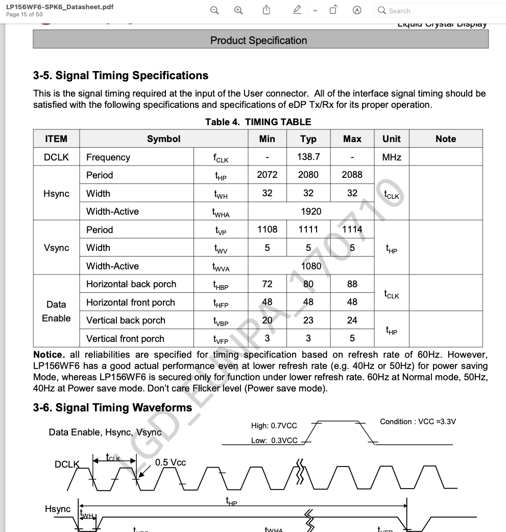
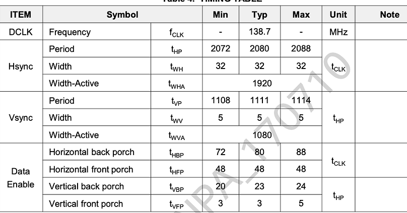
display-timings {
native-mode = <&timing0>;
timing0: timing0 {
clock-frequency = <145500000>;
hactive = <1920>;
vactive = <1080>;
hfront-porch = <48>;
hsync-len = <32>;
hback-porch = <80>;
vfront-porch = <3>;
vsync-len = <5>;
vback-porch = <23>;
hsync-active = <0>;
vsync-active = <0>;
de-active = <0>;
pixelclk-active = <0>;
};
};
};
rt5651-sound {
status = "okay";
compatible = "simple-audio-card";
pinctrl-names = "default";
pinctrl-0 = <&rt5651_hpdet>;
simple-audio-card,format = "i2s";
simple-audio-card,name = "realtek,rt5651-codec";
simple-audio-card,mclk-fs = <256>;
simple-audio-card,hp-det-gpio = <&gpio1 0 GPIO_ACTIVE_HIGH>;
simple-audio-card,widgets =
"Microphone", "Mic Jack",
"Headphone", "Headphone Jack";
simple-audio-card,routing =
"Mic Jack", "MICBIAS1",
"IN1P", "Mic Jack",
"Headphone Jack", "HPOL",
"Headphone Jack", "HPOR";
simple-audio-card,cpu {
sound-dai = <&i2s1>;
};
simple-audio-card,codec {
sound-dai = <&rt5651>;
};
};
};
&fusb0 {
status = "okay";
max-input-voltage = <13000000>;
max-input-current = <6000000>;
charge-dev = <&bq25703>;
};
&fusb1 {
status = "okay";
max-input-voltage = <13000000>;
max-input-current = <6000000>;
charge-dev = <&bq25703>;
};
&i2s1 {
status = "okay";
rockchip,i2s-broken-burst-len;
rockchip,playback-channels = <2>;
rockchip,capture-channels = <2>;
#sound-dai-cells = <0>;
};
&isp0_mmu {
status = "okay";
};
&isp1_mmu {
status = "okay";
};
&i2c0 {
status = "okay";
i2c-scl-rising-time-ns = <300>;
i2c-scl-falling-time-ns = <15>;
};
&i2c1 {
status = "okay";
i2c-scl-rising-time-ns = <300>;
i2c-scl-falling-time-ns = <15>;
rt5651: rt5651@1a {
#sound-dai-cells = <0>;
compatible = "rockchip,rt5651";
reg = <0x1a>;
clocks = <&cru SCLK_I2S_8CH_OUT>;
clock-names = "mclk";
pinctrl-names = "default";
pinctrl-0 = <&i2s_8ch_mclk>;
status = "okay";
};
};
&i2c6 {
status = "okay";
vm149c: vm149c@0c {
compatible = "silicon touch,vm149c";
status = "okay";
reg = <0x0c>;
rockchip,camera-module-index = <0>;
rockchip,camera-module-facing = "back";
};
imx214b: imx214b@10 {
compatible = "sony,imx214";
status = "okay";
reg = <0x10>;
clocks = <&cru SCLK_CIF_OUT>;
clock-names = "xvclk";
/* avdd-supply = <>; */
/* dvdd-supply = <>; */
/* dovdd-supply = <>; */
/* reset-gpios = <>; */
pwdn-gpios = <&gpio2 5 GPIO_ACTIVE_HIGH>;
reset-gpios = <&gpio2 12 GPIO_ACTIVE_HIGH>;
pinctrl-names = "rockchip,camera_default";
pinctrl-0 = <&cif_clkout>;
rockchip,camera-module-index = <0>;
rockchip,camera-module-facing = "back";
rockchip,camera-module-name = "YG9626-S600Y7-C";
rockchip,camera-module-lens-name = "LG-50013A7";
lens-focus = <&vm149c>;
port {
ucam_out0: endpoint {
remote-endpoint = <&mipi_in_ucam0>;
//remote-endpoint = <&mipi_in_ucam1>;
data-lanes = <1 2>;
};
};
};
vm149c_front: vm149c_front@0c {
compatible = "silicon touch,vm149c";
status = "okay";
reg = <0x0c>;
rockchip,camera-module-index = <1>;
rockchip,camera-module-facing = "front";
};
imx214f: imx214f@10 {
compatible = "sony,imx214";
status = "okay";
reg = <0x10>;
clocks = <&cru SCLK_CIF_OUT>;
clock-names = "xvclk";
/* avdd-supply = <>; */
/* dvdd-supply = <>; */
/* dovdd-supply = <>; */
/* reset-gpios = <>; */
pwdn-gpios = <&gpio2 12 GPIO_ACTIVE_HIGH>;
reset-gpios = <&gpio2 5 GPIO_ACTIVE_HIGH>;
pinctrl-names = "rockchip,camera_default";
pinctrl-0 = <&cif_clkout>;
rockchip,camera-module-index = <1>;
rockchip,camera-module-facing = "front";
rockchip,camera-module-name = "YG9626-S600Y7-C";
rockchip,camera-module-lens-name = "LG-50013A7";
lens-focus = <&vm149c_front>;
port {
ucam_out1: endpoint {
//remote-endpoint = <&mipi_in_ucam0>;
remote-endpoint = <&mipi_in_ucam1>;
data-lanes = <1 2>;
};
};
};
};
&i2c7 {
status = "okay";
icm20602_acc: icm_acc@68 {
compatible = "icm20602_acc";
reg = <0x68>;
irq-gpio = <&gpio0 8 IRQ_TYPE_LEVEL_LOW>; /* GPIO0_B0 */
irq_enable = <0>;
poll_delay_ms = <30>;
type = <SENSOR_TYPE_ACCEL>;
layout = <9>;
};
icm20602_gyro: icm_gyro@68 {
compatible = "icm20602_gyro";
reg = <0x68>;
irq_enable = <0>;
poll_delay_ms = <30>;
type = <SENSOR_TYPE_GYROSCOPE>;
layout = <7>;
};
};
&i2c8 {
status = "okay";
i2c-scl-rising-time-ns = <600>;
i2c-scl-falling-time-ns = <20>;
apds9960@39 {
compatible = "avago,apds9960";
reg = <0x39>;
interrupt-parent = <&gpio3>;
interrupts = <RK_PB2 IRQ_TYPE_LEVEL_LOW>;
led-r-gpio = <&gpio4 24 GPIO_ACTIVE_HIGH>;
pinctrl-names = "default";
pinctrl-0 = <&apds_int_l>;
};
bq25703: bq25703@6b {
compatible = "ti,bq25703";
reg = <0x6b>;
extcon = <&fusb0>, <&fusb1>;
interrupt-parent = <&gpio1>;
interrupts = <RK_PC7 IRQ_TYPE_LEVEL_LOW>; /* GPIO1_C7 */
pinctrl-names = "default";
pinctrl-0 = <&charger_ok>;
ti,charge-current = <1500000>;
ti,max-charge-voltage = <8500000>;
ti,max-input-voltage = <20000000>;
ti,max-input-current = <6000000>;
ti,input-current-sdp = <500000>;
ti,input-current-dcp = <2000000>;
ti,input-current-cdp = <2000000>;
ti,input-current-dc = <2000000>;
ti,minimum-sys-voltage = <7400000>;
ti,otg-voltage = <5000000>;
ti,otg-current = <500000>;
ti,input-current = <500000>;
pd-charge-only = <0>;
status = "okay";
};
cw2013: cw2013@62 {
status = "okay";
compatible = "cw201x";
reg = <0x62>;
bat_config_info = <0x15 0x7F 0x6E 0x66 0x65 0x5C 0x5B 0x59
0x58 0x57 0x57 0x54 0x53 0x51 0x4B 0x48
0x40 0x33 0x2A 0x26 0x23 0x25 0x2A 0x34
0x45 0x4F 0x0C 0xCD 0x44 0x68 0x67 0x68
0x6E 0x6F 0x6C 0x68 0x3A 0x10 0x8A 0x01
0x01 0x54 0x52 0x87 0x8F 0x91 0x94 0x52
0x82 0x8C 0x92 0x96 0x82 0xFF 0xFF 0xCB
0x2F 0x7D 0x64 0xA5 0xB5 0x13 0x58 0x09>;
monitor_sec = <5>;
virtual_power = <0>;
divider_res1 = <200>;
divider_res2 = <200>;
dc_det_gpio = <&gpio1 RK_PC7 GPIO_ACTIVE_HIGH>;
};
};
&rk_key {
enter-key {
linux,code = <232>;
label = "enter";
rockchip,adc_value = <170>;
};
};
&pwm3 {
status = "okay";
interrupts = <GIC_SPI 61 IRQ_TYPE_LEVEL_HIGH 0>;
compatible = "rockchip,remotectl-pwm";
remote_pwm_id = <3>;
handle_cpu_id = <1>;
remote_support_psci = <1>;
pinctrl-names = "default";
pinctrl-0 = <&pwm3b_pin>;
ir_key1 {
rockchip,usercode = <0xff00>;
rockchip,key_table =
<0xeb KEY_POWER>,
<0xec KEY_MENU>,
<0xfc KEY_UP>,
<0xfd KEY_DOWN>,
<0xf1 KEY_LEFT>,
<0xe5 KEY_RIGHT>,
<0xf8 232>,
<0xa7 KEY_VOLUMEDOWN>,
<0xa3 388>, //mouse func
<0xa4 388>, //mouse func
<0xf4 KEY_VOLUMEUP>,
<0xfe KEY_BACK>,
<0xb7 KEY_HOME>;
};
};
&backlight {
pwms = <&pwm1 0 25000 0>;
status = "okay";
};
&pwm1 {
status = "okay";
};
&cdn_dp {
status = "disabled";
};
&dp_in_vopl {
status = "disabled";
};
&dp_in_vopb {
status = "disabled";
};
&hdmi_in_vopl {
status = "okay";
};
&hdmi_in_vopb {
status = "disabled";
};
&route_hdmi {
status = "okay";
connect = <&vopl_out_hdmi>;
};
&vopb {
status = "okay";
assigned-clocks = <&cru DCLK_VOP0_DIV>;
assigned-clock-parents = <&cru PLL_CPLL>;
};
&vopl {
status = "okay";
assigned-clocks = <&cru DCLK_VOP1_DIV>;
assigned-clock-parents = <&cru PLL_VPLL>;
};
&route_edp {
status = "okay";
connect = <&vopb_out_edp>;
};
&edp_in_vopl {
status = "disabled";
};
&edp_in_vopb {
status = "okay";
};
&edp {
force-hpd;
status = "okay";
ports {
edp_out: port@1 {
reg = <1>;
#address-cells = <1>;
#size-cells = <0>;
edp_out_panel: endpoint@0 {
reg = <0>;
remote-endpoint = <&panel_in_edp>;
};
};
};
};
&i2c2 {
status = "okay";
i2c-scl-rising-time-ns = <600>;
i2c-scl-falling-time-ns = <20>;
ft5336@38 {
compatible = "edt,edt-ft5336", "ft5x06";
reg = <0x38>;
interrupt-parent = <&gpio2>;
interrupts = <2 IRQ_TYPE_EDGE_FALLING>;
reset-gpio = <&gpio2 RK_PA3 GPIO_ACTIVE_HIGH>; /* GPIO2_A3 */
status = "disabled";
};
};
&pinctrl {
matrix {
matrix_gpio: matrix_gpio {
rockchip,pins =
<0 10 RK_FUNC_GPIO &pcfg_pull_up>,
<0 11 RK_FUNC_GPIO &pcfg_pull_up>,
<0 12 RK_FUNC_GPIO &pcfg_pull_up>;
};
};
apds_int_l: apds-int-l {
rockchip,pins = <3 10 RK_FUNC_GPIO &pcfg_pull_up>;
};
charger {
charger_ok: charge-ok {
rockchip,pins = <1 RK_PC7 RK_FUNC_GPIO &pcfg_pull_up>; /* GPIO1_C7 */
};
};
rt5651 {
rt5651_hpdet: rt5651-hpdet {
rockchip,pins = <1 0 RK_FUNC_GPIO &pcfg_pull_up>; /* GPIO1_A0 */
};
};
};
&mipi_dphy_rx0 {
status = "okay";
ports {
#address-cells = <1>;
#size-cells = <0>;
port@0 {
reg = <0>;
#address-cells = <1>;
#size-cells = <0>;
mipi_in_ucam0: endpoint@1 {
reg = <1>;
remote-endpoint = <&ucam_out0>;
data-lanes = <1 2>;
};
};
port@1 {
reg = <1>;
#address-cells = <1>;
#size-cells = <0>;
dphy_rx0_out: endpoint@0 {
reg = <0>;
remote-endpoint = <&isp0_mipi_in>;
};
};
};
};
&rkisp1_0 {
status = "okay";
port {
#address-cells = <1>;
#size-cells = <0>;
isp0_mipi_in: endpoint@0 {
reg = <0>;
remote-endpoint = <&dphy_rx0_out>;
};
};
};
&mipi_dphy_tx1rx1 {
status = "okay";
ports {
#address-cells = <1>;
#size-cells = <0>;
port@0 {
reg = <0>;
#address-cells = <1>;
#size-cells = <0>;
mipi_in_ucam1: endpoint@1 {
reg = <1>;
remote-endpoint = <&ucam_out1>;
data-lanes = <1 2>;
};
};
port@1 {
reg = <1>;
#address-cells = <1>;
#size-cells = <0>;
dphy_tx1rx1_out: endpoint@0 {
reg = <0>;
remote-endpoint = <&isp1_mipi_in>;
};
};
};
};
&rkisp1_1 {
status = "okay";
port {
#address-cells = <1>;
#size-cells = <0>;
isp1_mipi_in: endpoint@0 {
reg = <0>;
remote-endpoint = <&dphy_tx1rx1_out>;
};
};
};
hlm@Server:/users/hlm/Rockcip_Android10.0_SDK/device/rockchip/rk3399$ git diff
diff --git a/rk3399_Android10/rk3399_Android10.mk b/rk3399_Android10/rk3399_Android10.mk
index 2e4831e..2b2d97a 100755
--- a/rk3399_Android10/rk3399_Android10.mk
+++ b/rk3399_Android10/rk3399_Android10.mk
@@ -51,8 +51,9 @@ PRODUCT_PROPERTY_OVERRIDES += \
        persist.vendor.sys.hdmiui=1 \
        persist.sys.rotation.einit=3 \
        persist.sys.app.rotation=force_land \
-    vendor.hwc.device.primary=HDMI-A,DP \
-    vendor.hwc.device.extend=DSI
+    vendor.hwc.device.primary=eDP \
+    vendor.hwc.device.extend=HDMI-A