Some elementary projects for the VIM. Most will work for VIM1 and VIM2, but always confirm connections and pin assignments with the appropriate schematic before making connections.
…
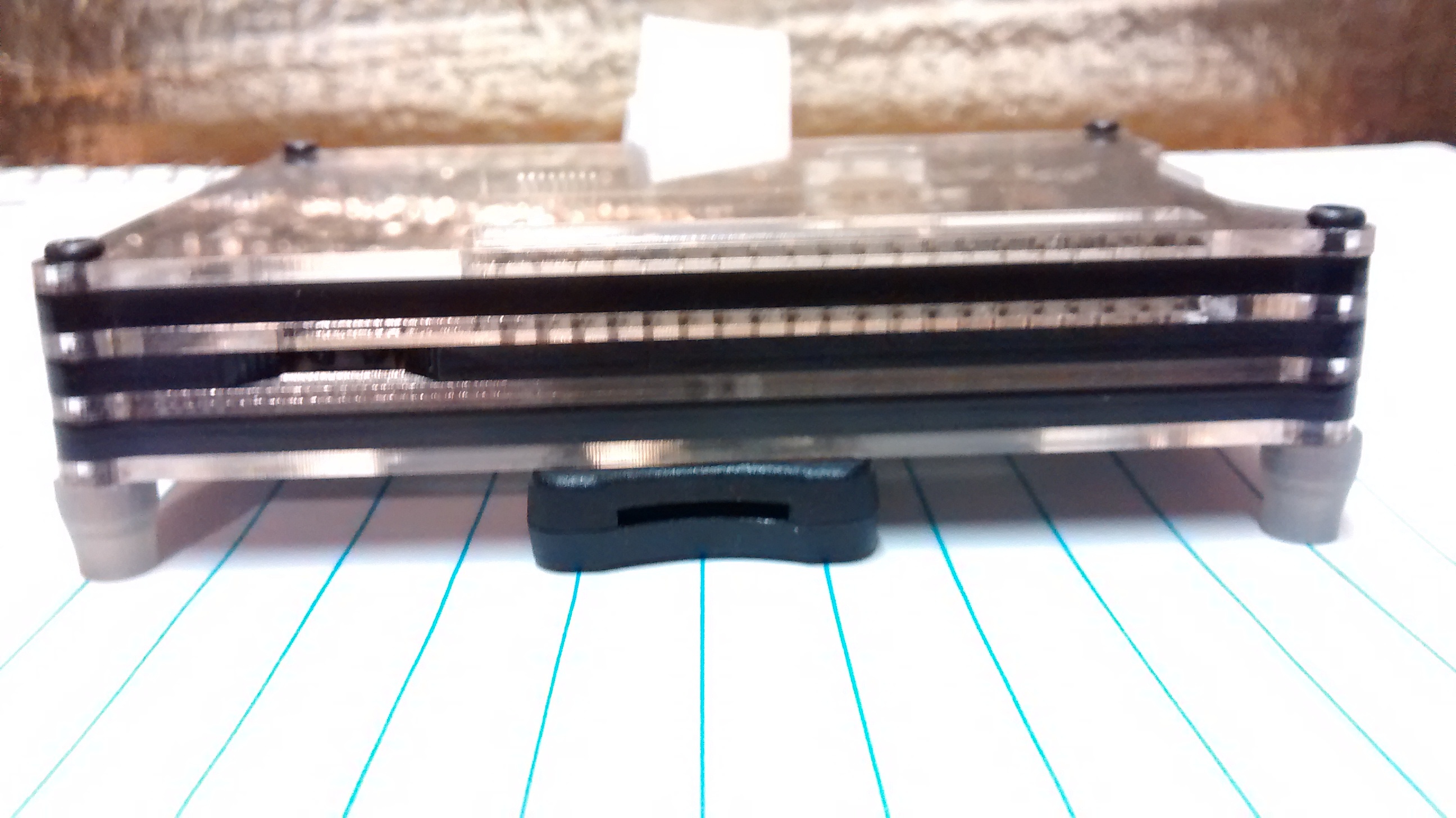
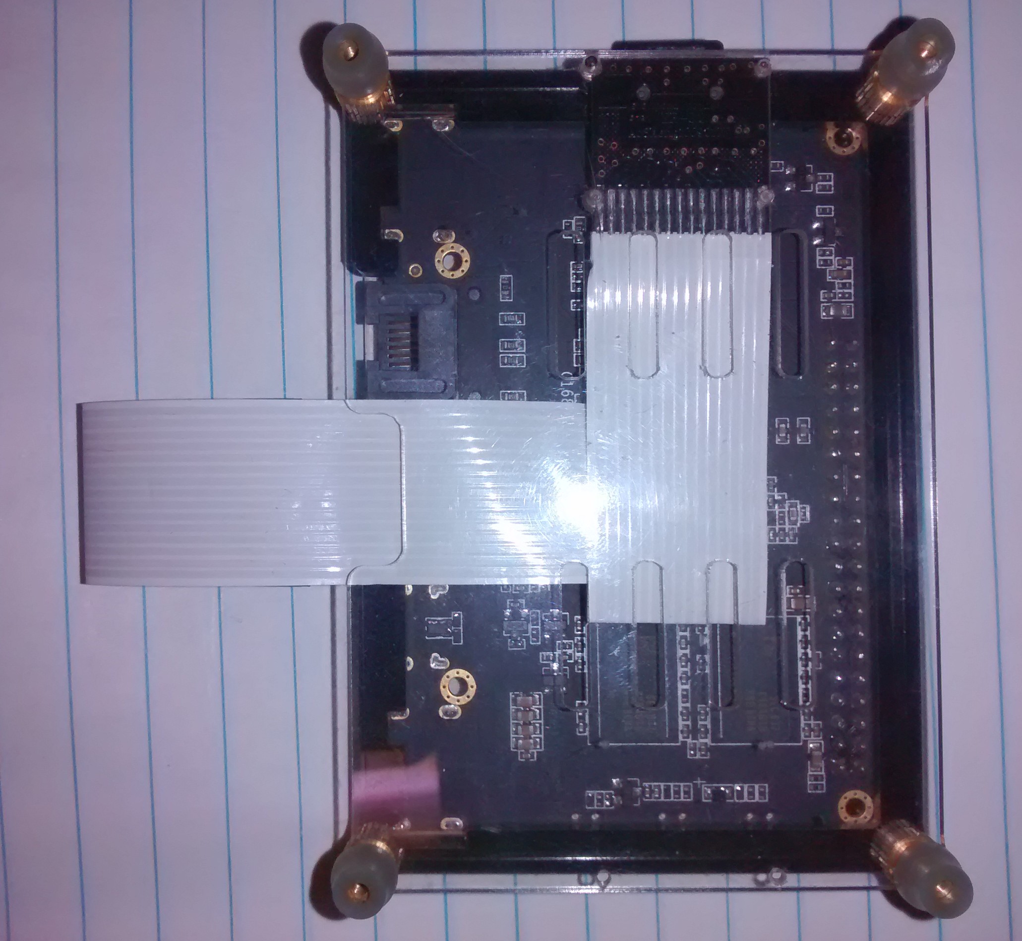
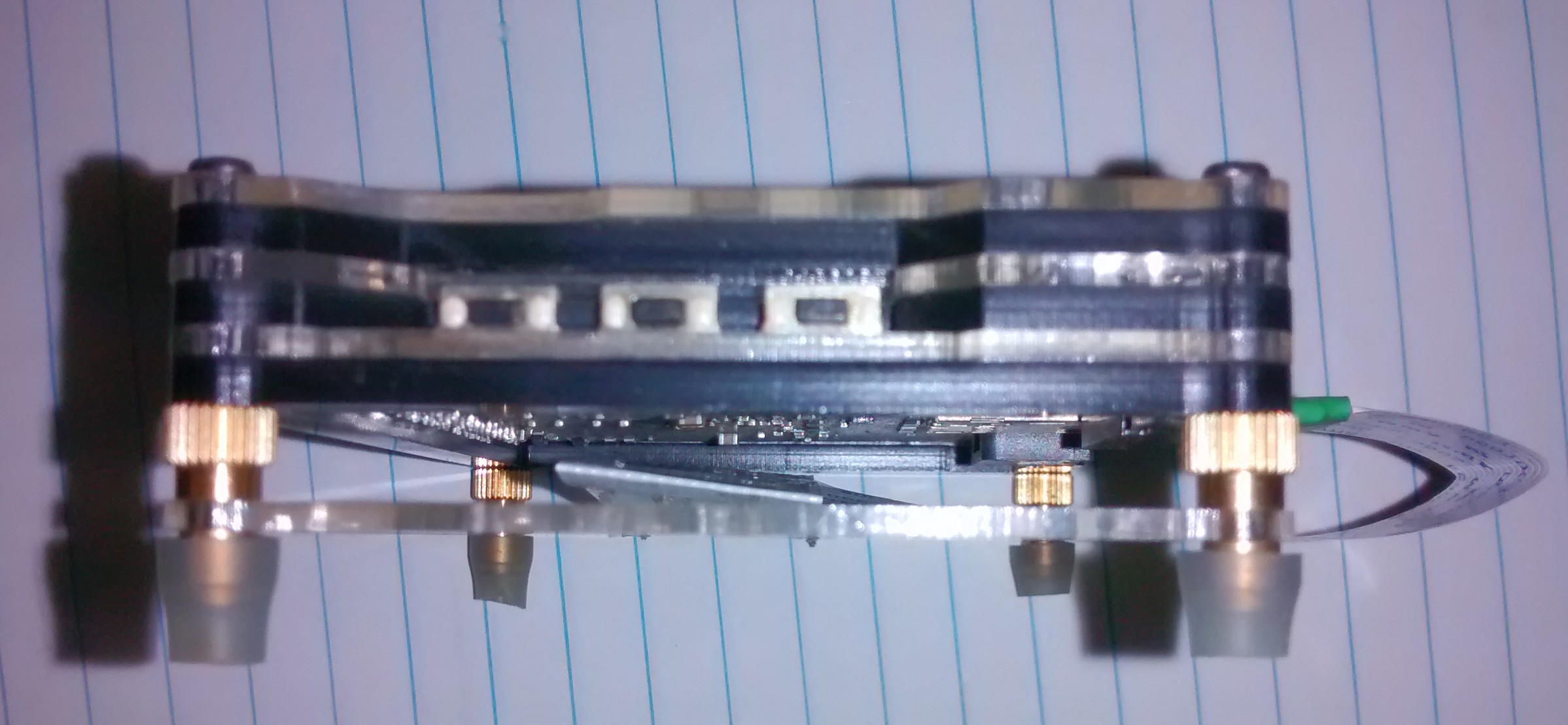
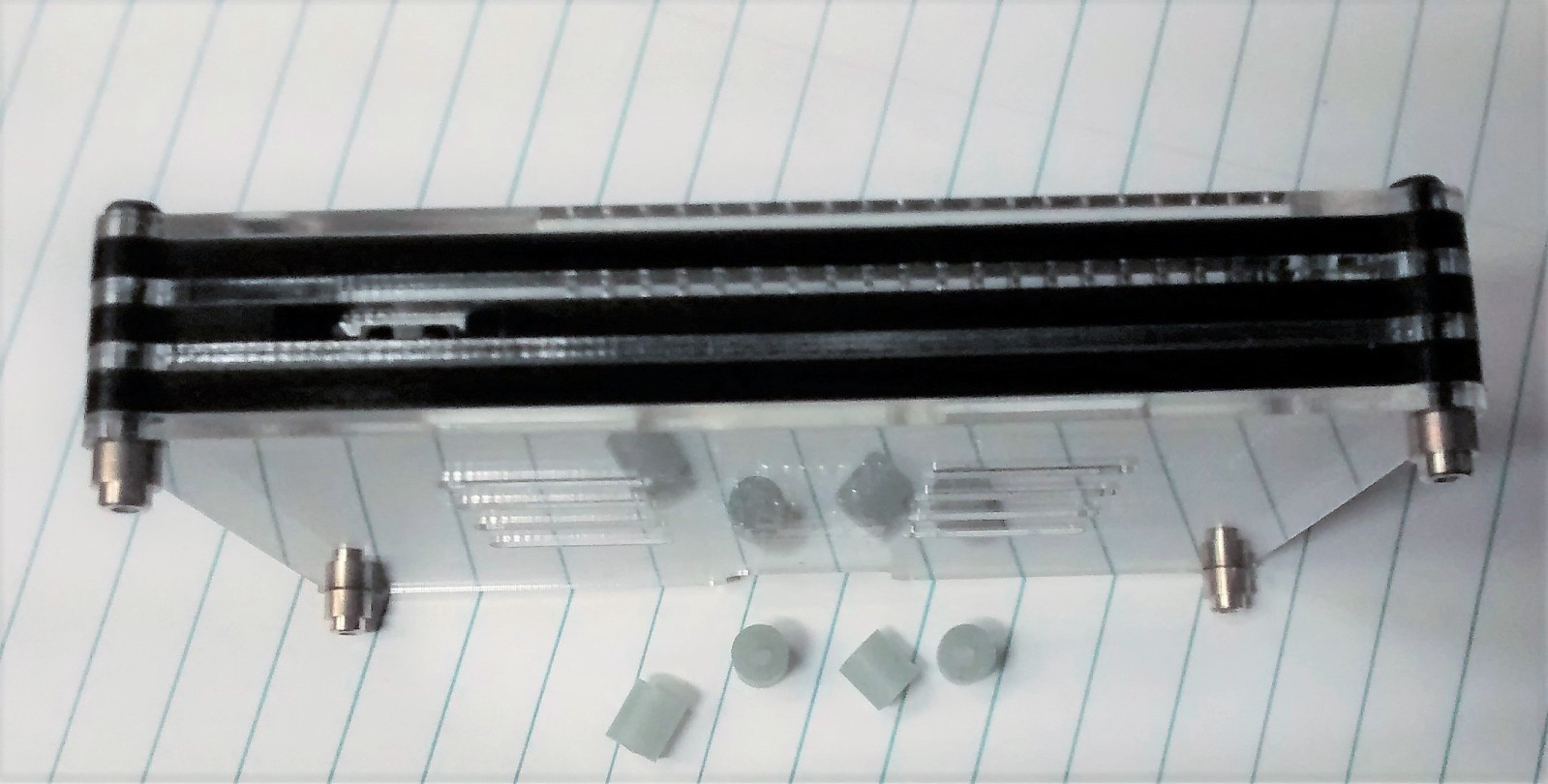
First project, Anti-Skid/Anti-Scratch feet for the VIM.
VimFeet
The VIM can be a little slippery of foot. The four threaded feet are great for holding the case together, but not for keeping the box in place on hard surfaces.
I used R/C model fuel line(silicone). Most types of silicone or rubber tubing would also work, A 24-25mm piece is all that is needed.
1.) Get fuel line or other appropriate tubing.
2.) From a 24-25mm piece, cut four even sections.
3.) Push tubing sections on to the four threaded feet.

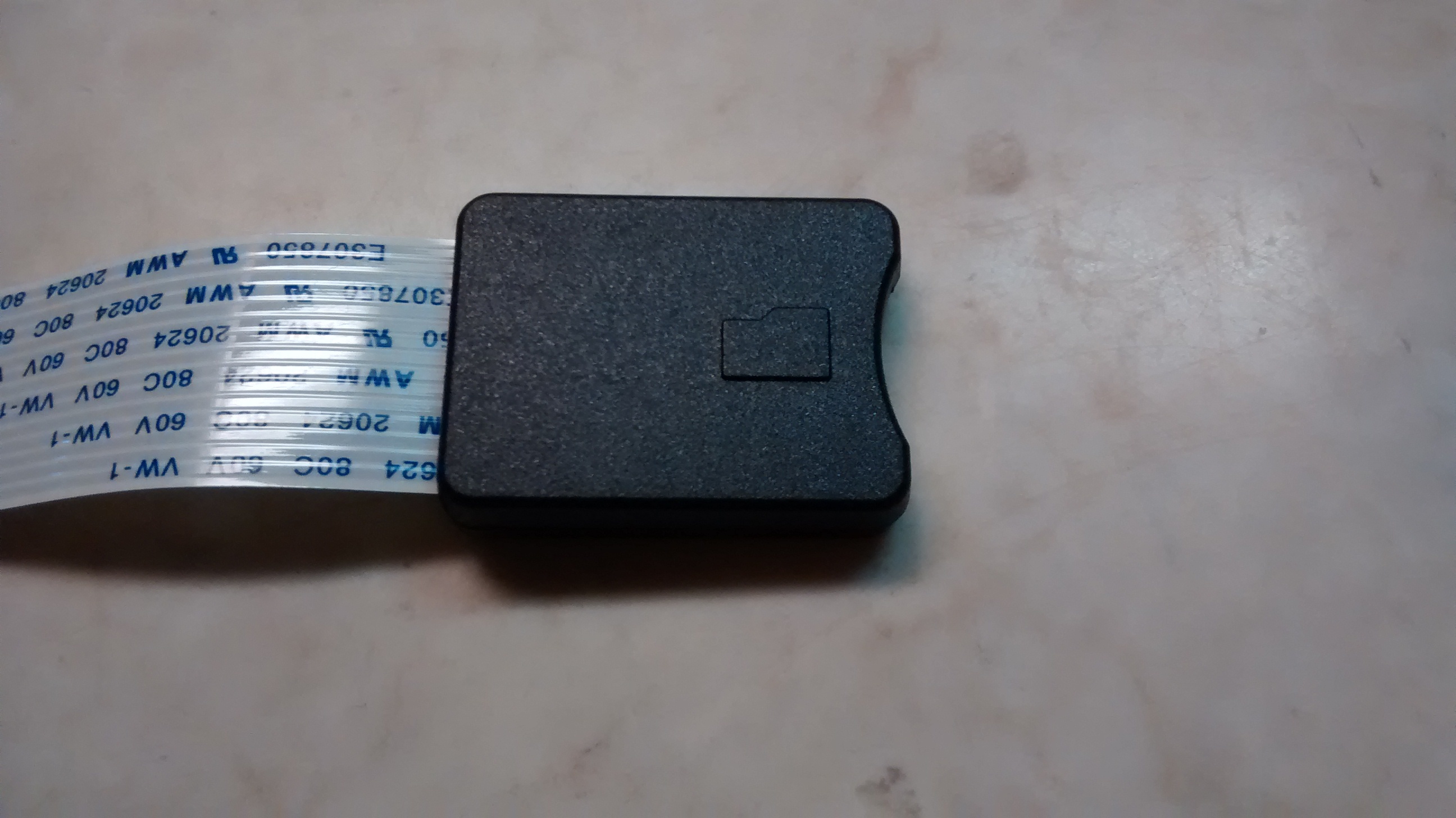
Second Project, easier access to the power button.
VimFingrelief
The VIM is a small device. Getting at the power button can be a challenge.
1.) Disassemble the Vim’s case to isolate the top section
2.) Insert sanding drum in to Dremel or similar handheld rotary tool. Use a low speed, you want to sand, not melt.
3.) Mark off the section to be relieved, or if you are feeling risky, just eyeball it as I did.
4.) Remove material until your mark is met or you eyeball is satisfied.
5.) Reassemble the VIM’s case and test.

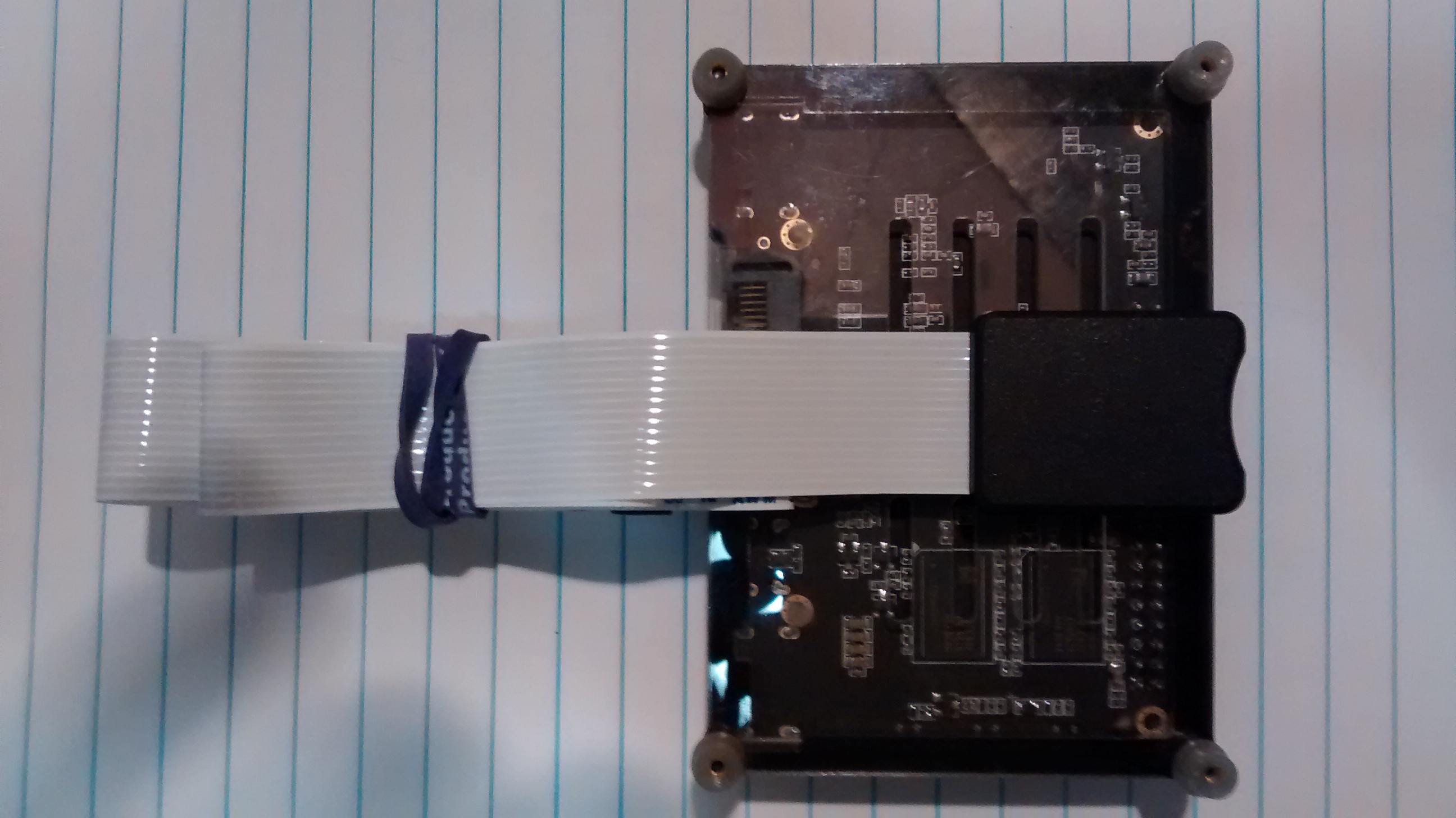
Third project, more USB Ports.
VIMUstension
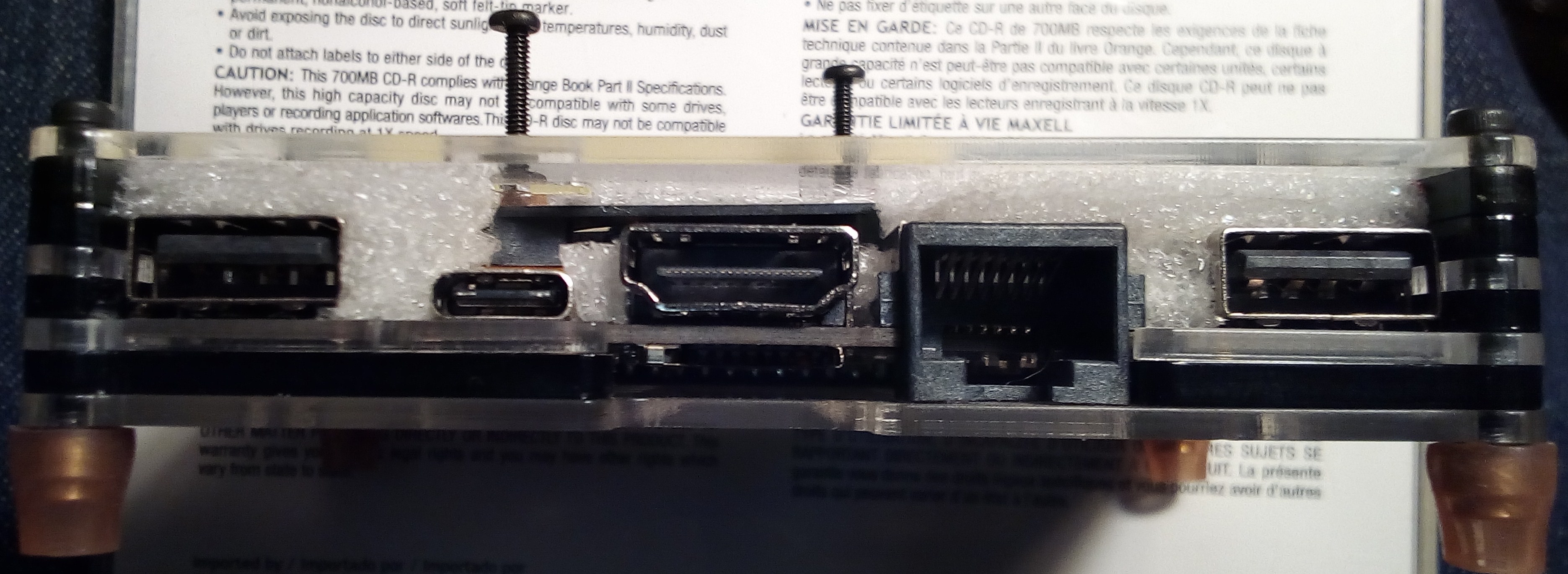
The VIM offers two USB ports on the rear, and an OTG USB-C port, but that port is usually supplying power to the VIM, so we have two.
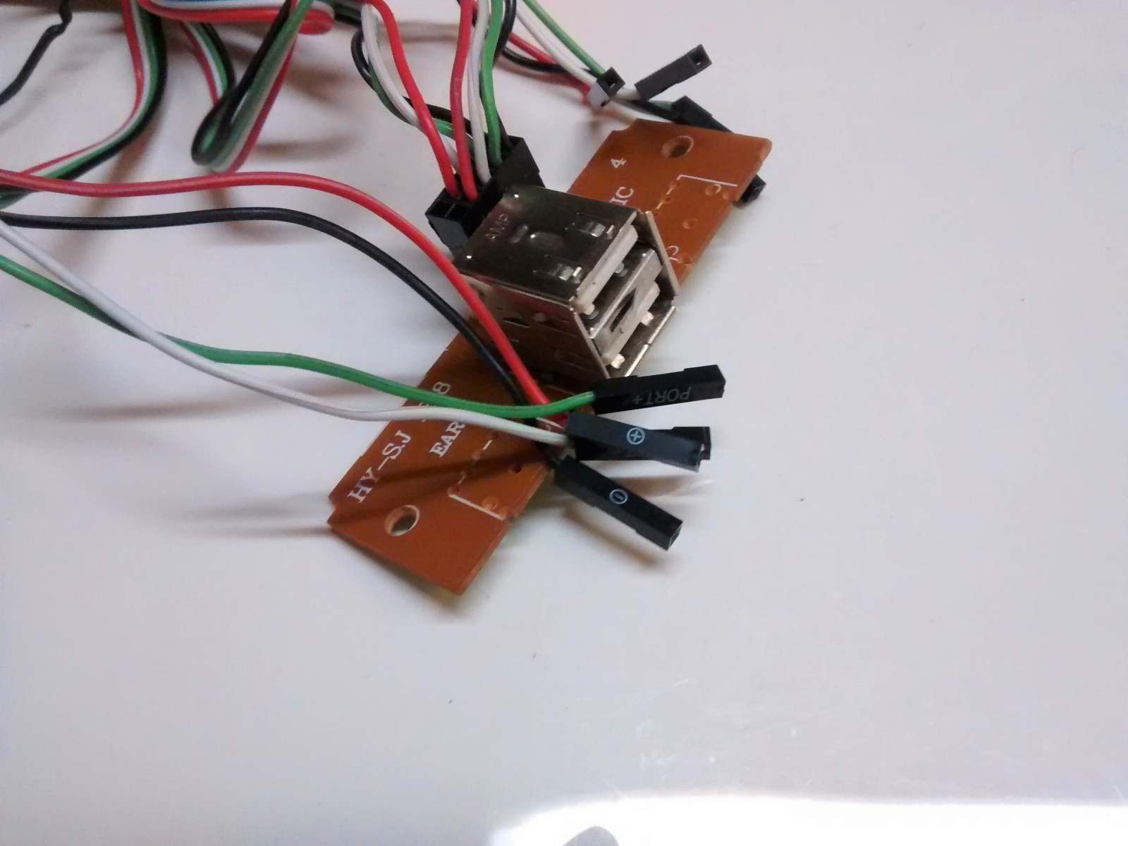
Fortunately, the GPIO offers two additional USB Ports(each with a 500mA maximum). An old PC case offered a remote USB port extension, complete with conveniently labeled board connectors.
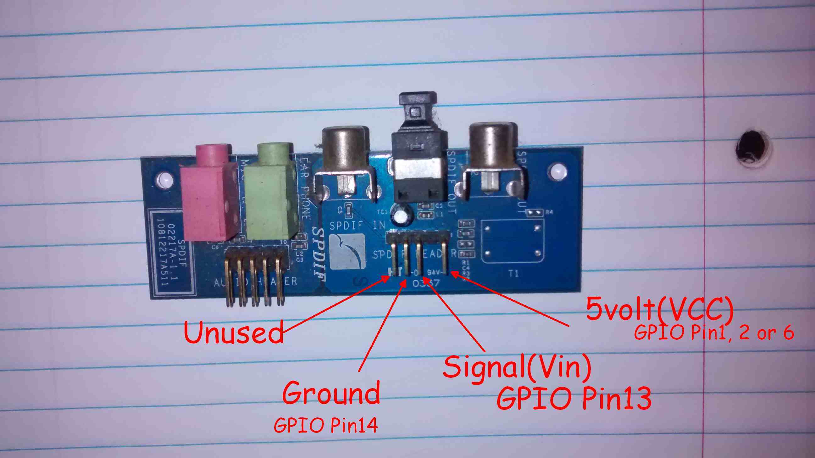
1.) Observe the GPIO pinout below.
2,) Locate an old PC case with a remote USB extension. Remove the extension.
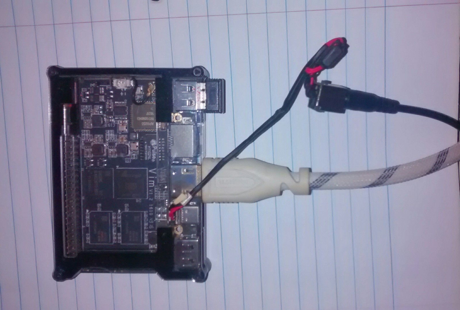
3.) Connect board connectors to the GPIO’s relevant pins(see step 1).


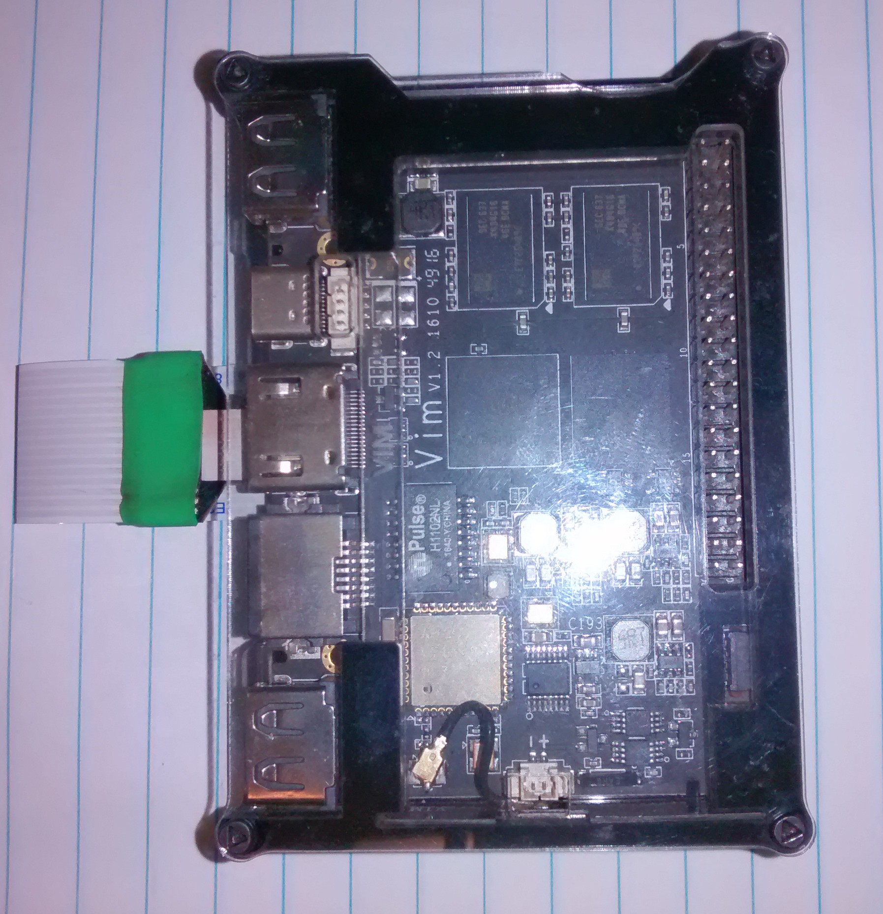
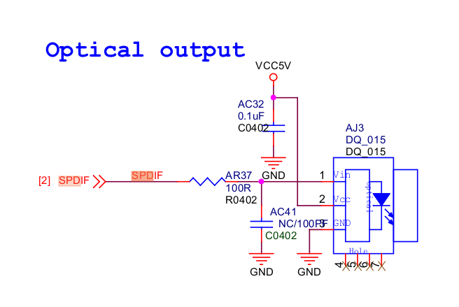
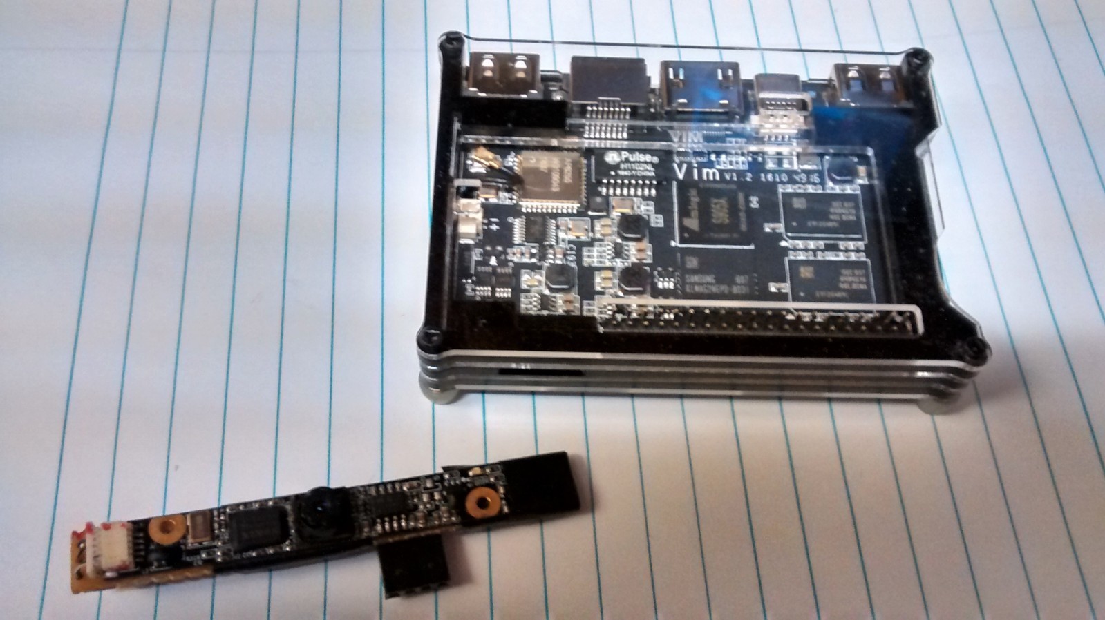
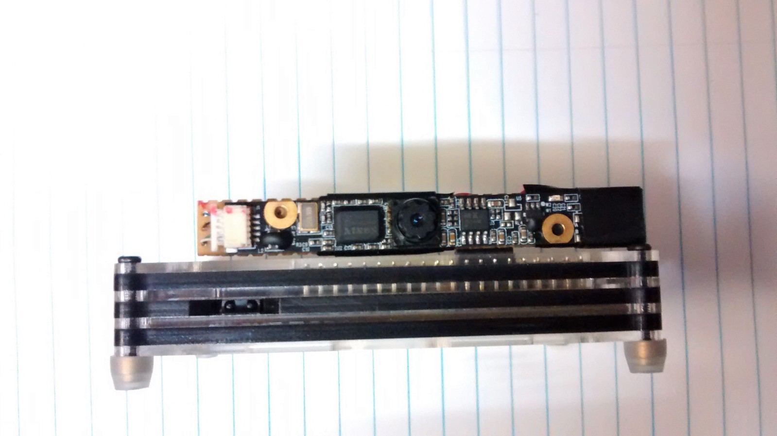
Fourth project, Giving the VIM sight.
VimCam
I have several webcam modules pulled from non-functioning Laptops and Chromebooks.
1.) Locate and recover an unused Laptop’s webcam. The type we are looking for uses a common USB interface. These can be found on sites like Ebay for about $3(USD) and up. Many of these are VGA cameras. Good enough for a stealthy IP camera or room monitor.
2.) Cut a section of perfboard to use as the cameras backing.
3.) Observe the GPIO USB Pinout from the VIMUstension project above.
4.) Using a 4 pin connector, you can recover one from the same case you recovered the USB ports for the VIMUstension project above
5.) Identify the appropriate USB pin locations from the GPIO. Identify the laptop camera module’s USB connections. Make the connections.
Please see this Instructables page for connection solutions and how-to.
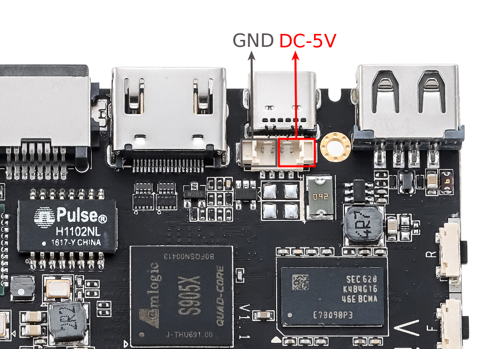
Caution: Most of these cameras are powered by 3.3 volts, the 5 volts on the GPIO’s USB Header may damage a 3.3v camera. I followed the Instructable(linked above) and put two diodes(1N1004 or similar) in series between the GPIO’s 5v pin and the camera’s USB power pin. A DC-to-DC converter could also be used.
3.3 volts is available on the GPIO. I did not use the 3.3 volt pin, because I wanted to keep the connector together.
Note: the Vim’s power LED can be turned off in settings, making for a fairly stealthy wireless IP camera(nanny cam).
Youtube video demonstrating function.
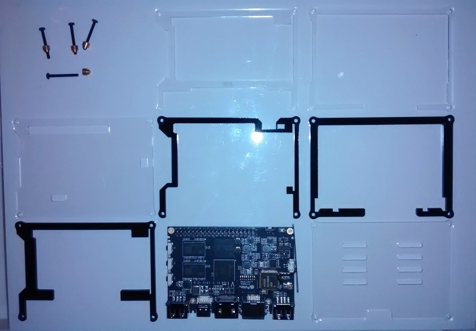
Fifth project, disassembling the VIM.
The case is bound by four-metal M2 screws(TA, tamper-resistant) mated to four M2 threaded metal “feet”. I did not have this bit in my collection. I found I could just hold pressure against the screw’s head with my thumb and remove the feet with pliers. You will want to provide something to protect the feet/case from the pliers, I used an old rag.