If it is possible. If you connect the fan to “RTC Battery slot” will it work ? The size of the fan connector fits into the connector RTC ? The power connector RTC is always present (with connected power supply) ?
Question on the radiator. You plan to add in future sets ? Is it possible to release two versions of the kits.
without the radiator
with radiator.
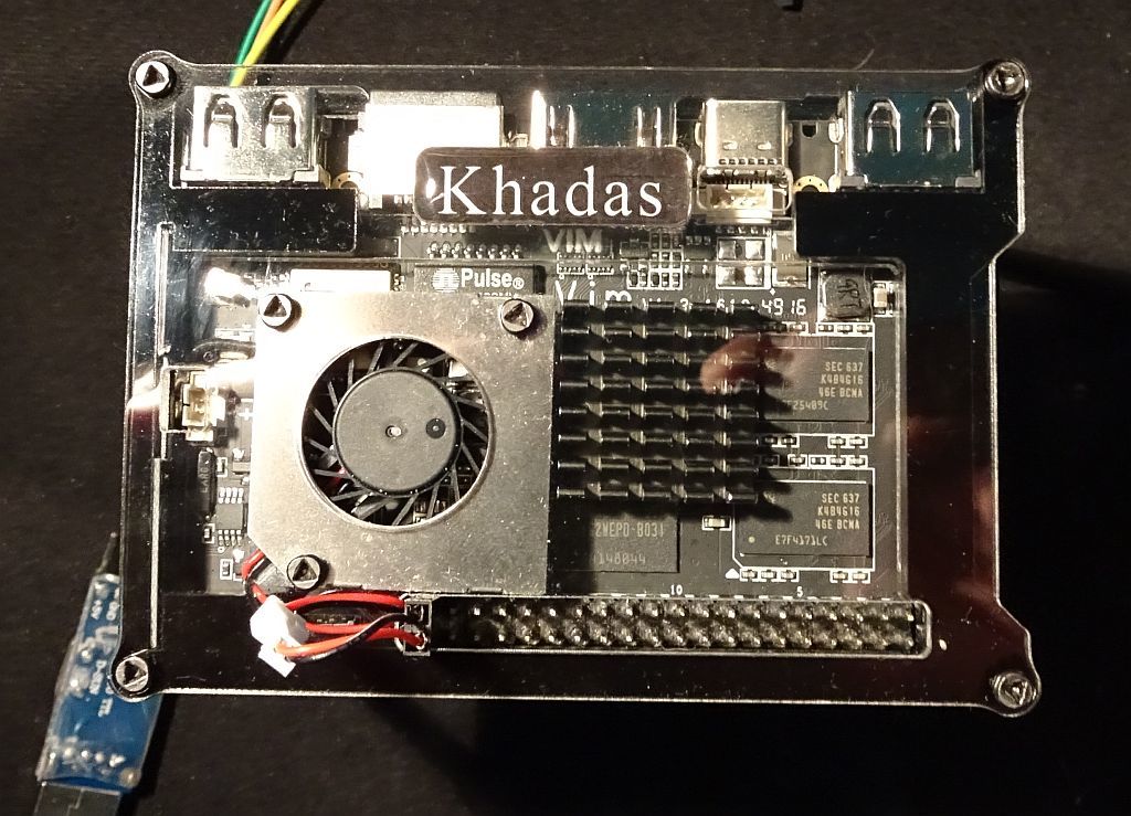
By the way, the mounting of the radiator can be easily solved without termoskotch. For better contact between the CPU and heatsink use thermal paste. If the top, between the radiator and the top plate of the case, to add a small piece of the elastic adhesive double-sided tape (NOT thermoskotch). The elastic strip is securely pressed against the radiator to the CPU and glued to the housing cover will not allow it to shift.
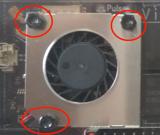
1.) Triangle-TA, tamper-resistant head. I have found on the case fasteners, these can be held with thumb pressure, while the nut is tightened with fingers, a wrench or pliers. Of course, when using metal fasteners in plastic, you don’t want it too tight anyway. Picture from here.
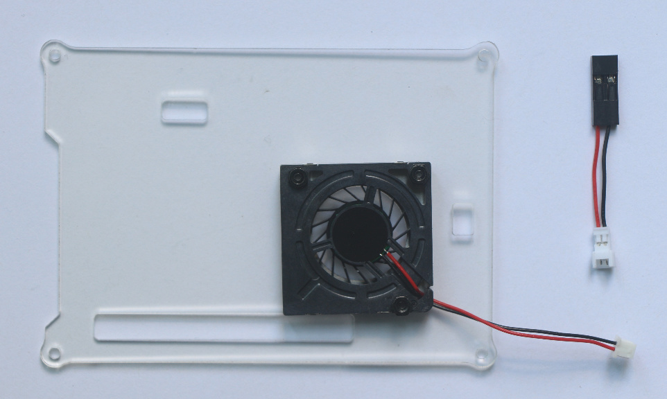
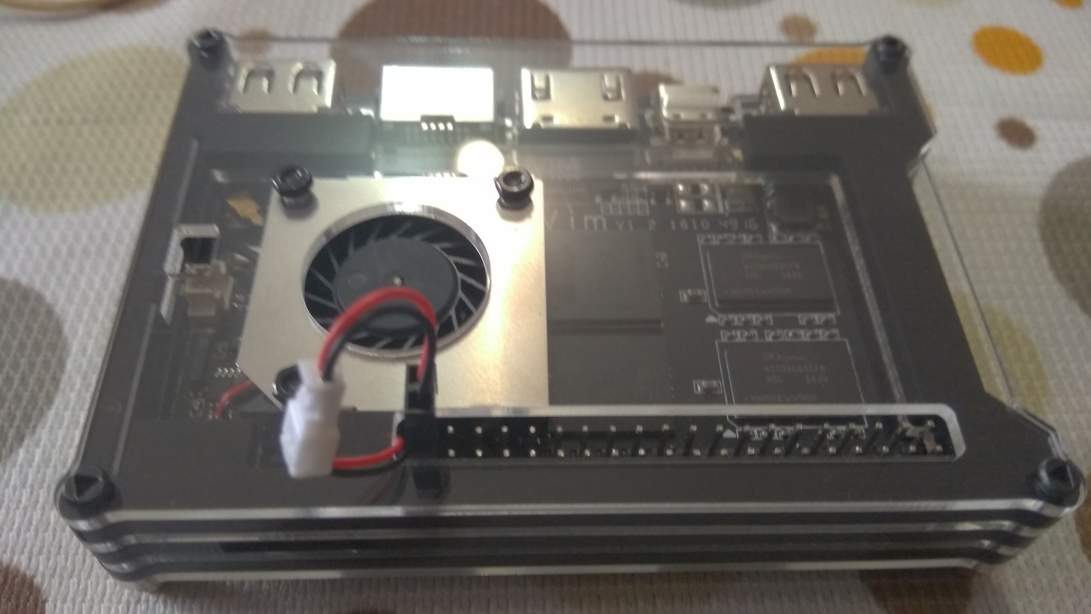
Bend the pins 20\40 at an angle of 90 degrees to the left, that the contact was located parallel to the Board under the top cover. then all the wires you will be able to place in the housing. If possible, you can trim off the excess wire and solder the connector to the wires of the fan with minimum length (which would have been just enough to connect to the connector on the Board).
Another method for keeping the GPIO fan connect wires under the top plate.
A DuPont jumper is used for example here, though should be much the same for the fan’s connectors. Note: DuPont connector shells removed.
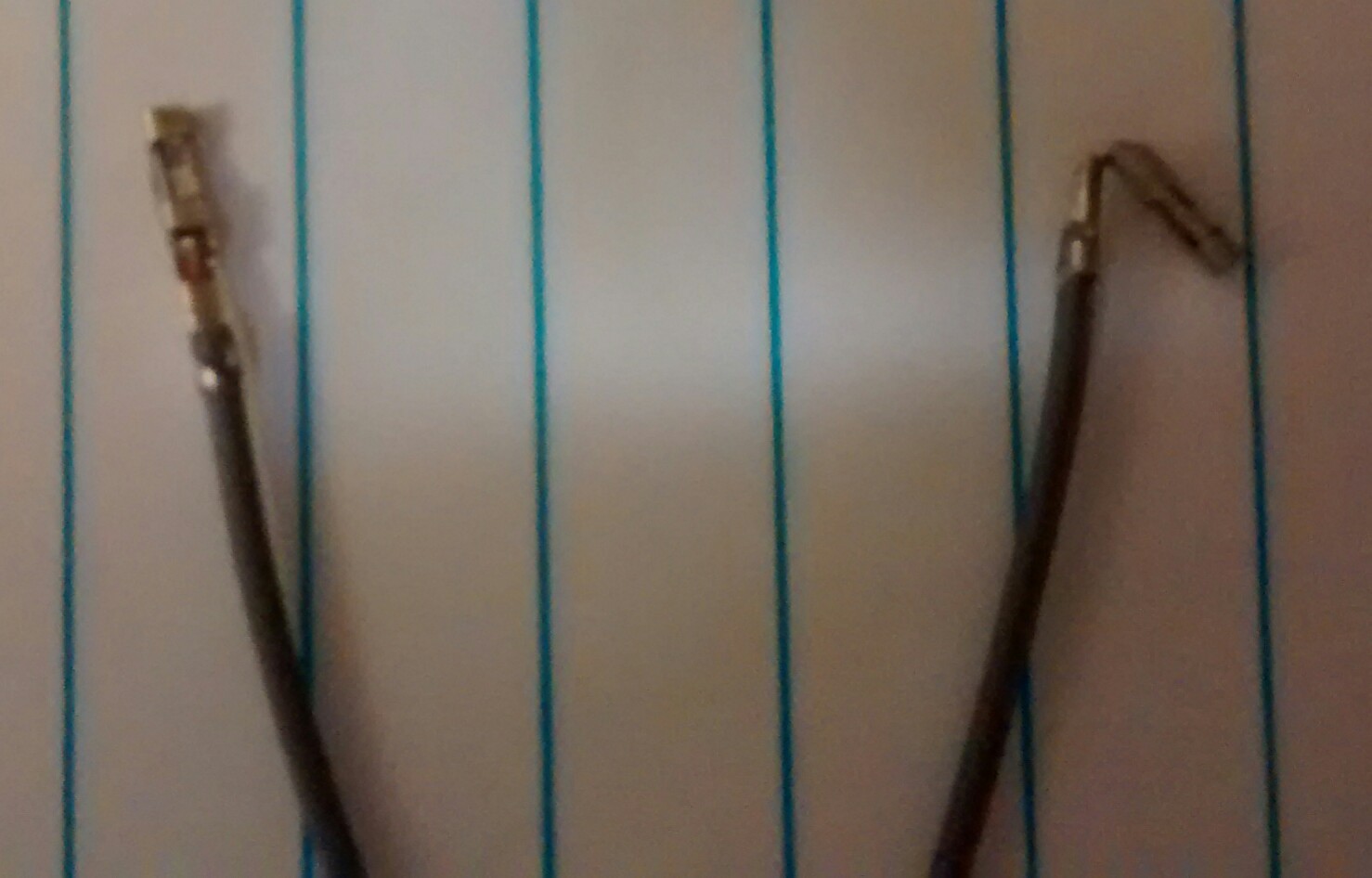
Caution should be exercised when bending thin metal to avoid a break. Bend slowly and avoid extreme right angle bends.
Before and after…
unacceptably loud for that small fan, or maybe my bad luck
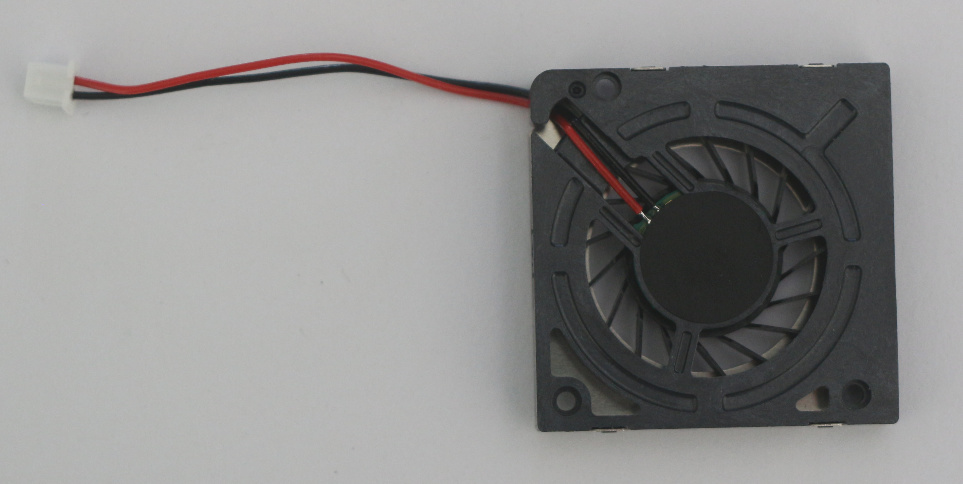
one may try to remove the black round sticker on top and it will give him three soldering points,suppose if you plan to use PWM to command the fan that is the right direction
did no further investigations on speed control - anyway too noisy for me
Hi, Abutkov:
Sorry for that, and @willow will follow up with the details.
Actually, you are exactly right for the feedback that to control the cooling fan with PWM. As when we designed the VIM, we just thought that cooling fan is not quite needed for VIM, so:
We didn’t design with an onboard 2-Pin slot for cooling fan
If need to be controlled by PWM for current VIM designing, we need design an external board/module spec with both power management and PWM and for that.
It seems that we might need to develop the module in the future.
Anyway, VIM2 will got better cooling fan supporting.
Hello. Abutkov. Sorry for this. How about the cooling fan, could it work?
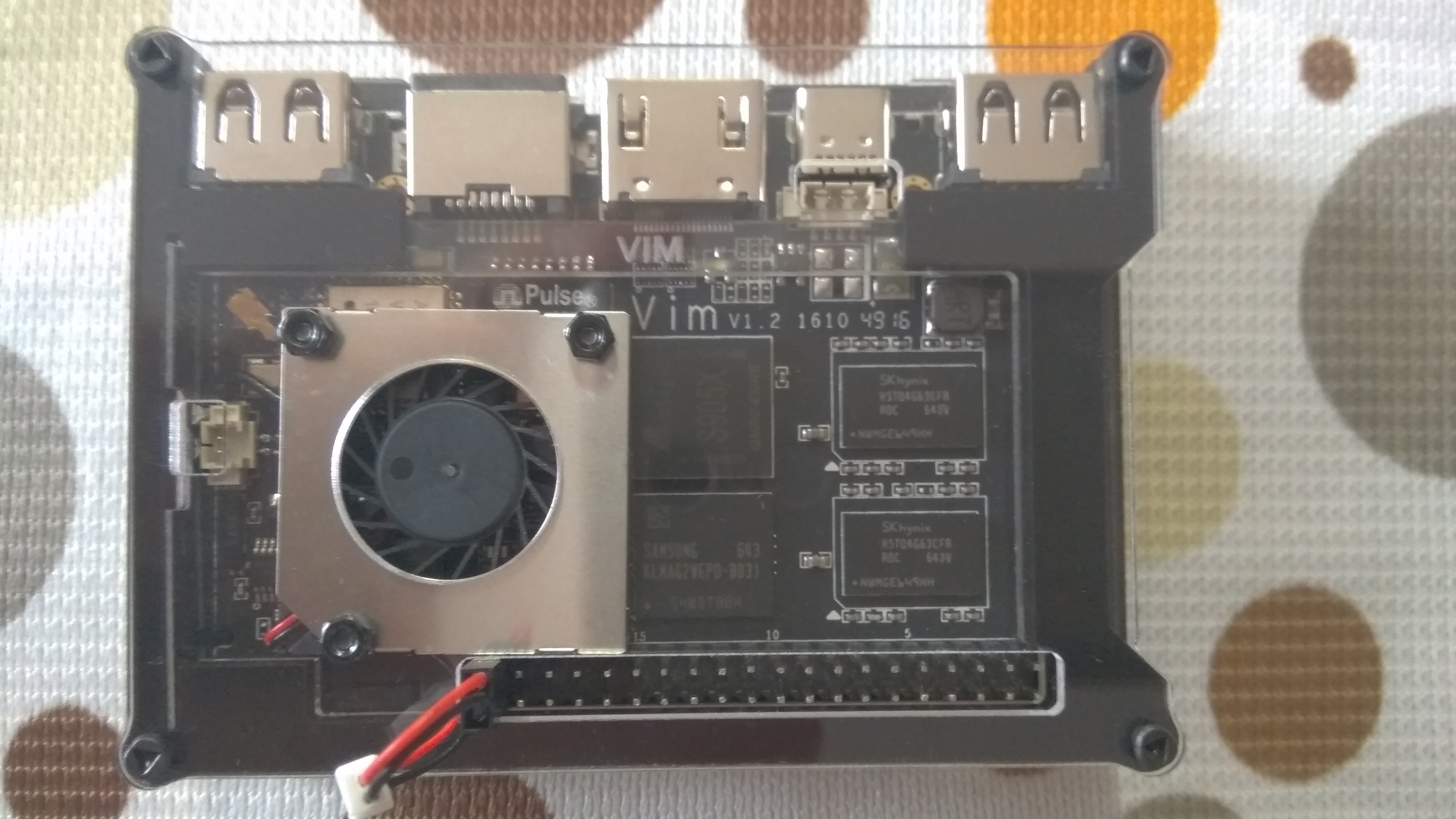
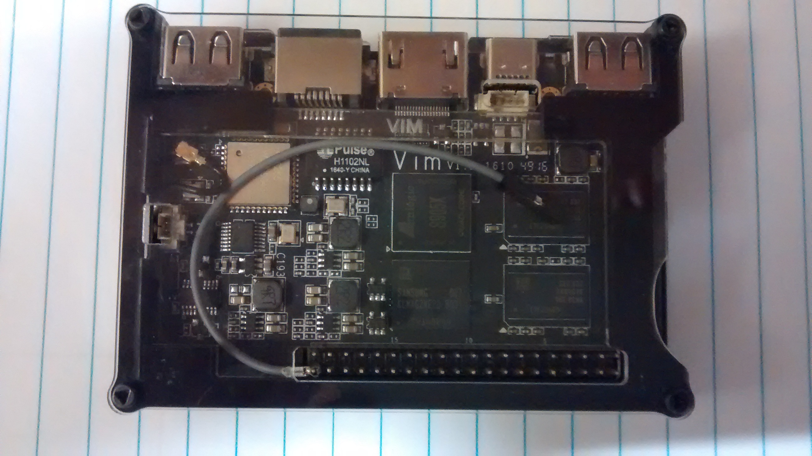
As i see on the picture, there is black and red small lines connected with the cooling fan, but from your picture they have gone. You did it and removed them to have a new try?
or it comes like that.
Hi, willow
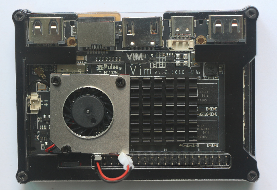
I simply desoldered 1.25mm converter lines to replace them directly with 2.54mm - to turn it more native
And then I went even further and soldered wires directly to the mainboard - just to make the appearance less exserted. So during these manipulations I noticed the 3rd soldering point and supposed it to be PWM (also see the yellow line on the picture above)
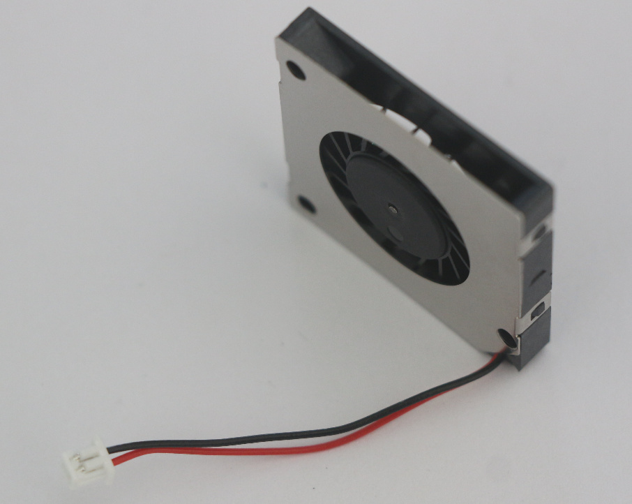
Anyway, the noise level was high for me and I didn’t look through the datasheet (kind of SUNON UB5U3-500) to check if my guess was true. As for the rest - blower in operating condition, so if this small server happen to move somewhere far it might retrive its cooling device.
add 1: it was noisy from the beginning, not the result of a hot iron, so now I have a better ventilated casing
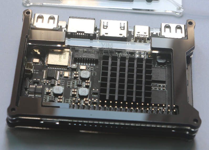
add 2: the screw DOES push the LAN transformer